Chapter 5
153
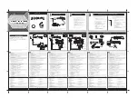
Jumper and Connector Locations
Mainboard Top View
Item
Description
Item
Description
PJ1
Battery connector
U40
PCH
U29. U30, U32, U34
VRAM connectors
CN21
Mini PCIe Connector
CN11
Fan connectors
CN18
HDD Connector
CN13
CRT connector
PJ2
DC-In Connector
CN15
HDMI connector
U33
GPU
CN16
RJ45
U37
CPU
CN17
USB
JDIMM2
DDR3 (CFD)
CN19
Microphone jack
JDIMM4
DDR3 (AFD, CFD)
CN20
SPIDF
JDIMM2
DDR3 (CFD)
U43
CODEC
JDIM2
DDR3 (ARD, CFD)
U44
Card Reader
PJ1
BATTER
CONN
U29,U30,U32,U34
VRAM
CN11 FAN CONN
PJ2
DC
Ͳ
IN
CONN
VRAM
U33
GPU
(11P,11M,11E)
CN11
FAN
CONN
CN14
ODD
CONN
(11P,11M,11E)
JDIM2
DDR3
(ARD,CFD)
JDIM2
DDR3
(CFD)
CN13
CRT
U37
CPU
(ARD,CFD)
JDIM4
DDR3
(AFD,CFD)
(
)
CN15
HDMI
(
)
CN18
HDD
CONN
JDIM2
DDR3
(CFD)
CN16
RJ45
CN17
USB
U40
PCH
U43
CODEC
CN19
MIC
JACK
CN21
MINI
PCIE
CONN
U44
CARD
READER
Controller
CN20
SPIDF
Chapter 5
Summary of Contents for ASPIRE 5745
Page 6: ...VI ...
Page 10: ...X Table of Contents ...
Page 48: ...38 Chapter 2 ...
Page 56: ...46 Chapter 3 4 Lift the base door out and away ...
Page 61: ...Chapter 3 51 5 Pull the WLAN module out and away ...
Page 74: ...64 Chapter 3 4 Unlock and disconnect the switch board FFC ...
Page 76: ...66 Chapter 3 4 Lift the power board away ...
Page 83: ...Chapter 3 73 5 Detach the Bluetooth module cable from the module ...
Page 98: ...88 Chapter 3 7 Disconnect the FPC cable ...
Page 102: ...92 Chapter 3 8 Pry the antenna off the casing ...
Page 105: ...Chapter 3 95 7 Lay the cables along the retention guides ...
Page 123: ...Chapter 3 113 4 Connect the Bluetooth module cable to the main board ...
Page 132: ...122 Chapter 3 7 Connect and lock the button board FFC ...
Page 138: ...128 Chapter 3 4 Grasp the tab and slide the HDD firmly into the docking connector ...
Page 141: ...Chapter 3 131 4 Push the ODD completely into the bay until flush with the lower cover ...
Page 162: ...152 Chapter 4 ...
Page 230: ...220 ...
Page 233: ...223 Index ...


