


Chapter 3
83
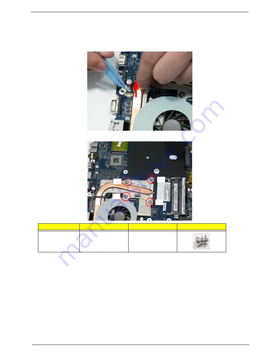
Removing the Thermal Module
1.
See “Removing the Mainboard” on page 80.
2.
Turn the Mainboard over and place on a clean surface.
3.
Hold the fan cable connector and lift to disconnect from the mainboard.
4.
Remove the four screws from the Thermal Module numerically, from 4 to 1.
Step
Size
Quantity
Screw Type
Thermal Module
M 2.5*3.2
4
1
4
3
2
Summary of Contents for Aspire 4240 Series
Page 6: ...VI ...
Page 10: ...X Table of Contents ...
Page 14: ...4 Chapter 1 System Block Diagram ...
Page 45: ...Chapter 2 35 A progress screen displays ...
Page 50: ...40 Chapter 2 2 In DOS mode run the MAC BAT file to write MAC values to eeprom ...
Page 57: ...Chapter 3 47 5 Remove the HDD Cover as shown ...
Page 98: ...88 Chapter 3 4 Lift the bezel away from the panel ...
Page 101: ...Chapter 3 91 4 Lift the LCD Panel out of the casing as shown ...
Page 125: ...Chapter 3 115 4 Replace the single securing screw ...
Page 146: ...136 Chapter 3 ...
Page 176: ...166 Chapter 5 ...
Page 189: ...Chapter 6 179 ...
Page 208: ...Appendix A 198 ...
Page 220: ...210 Appendix B ...
Page 222: ...212 Appendix C ...


