5-88
Service and Maintenance
2.
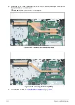
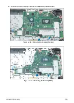
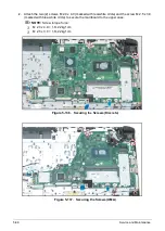
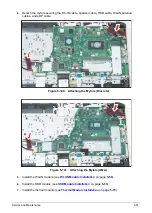
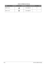
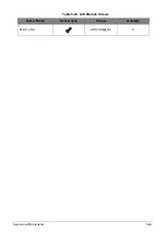
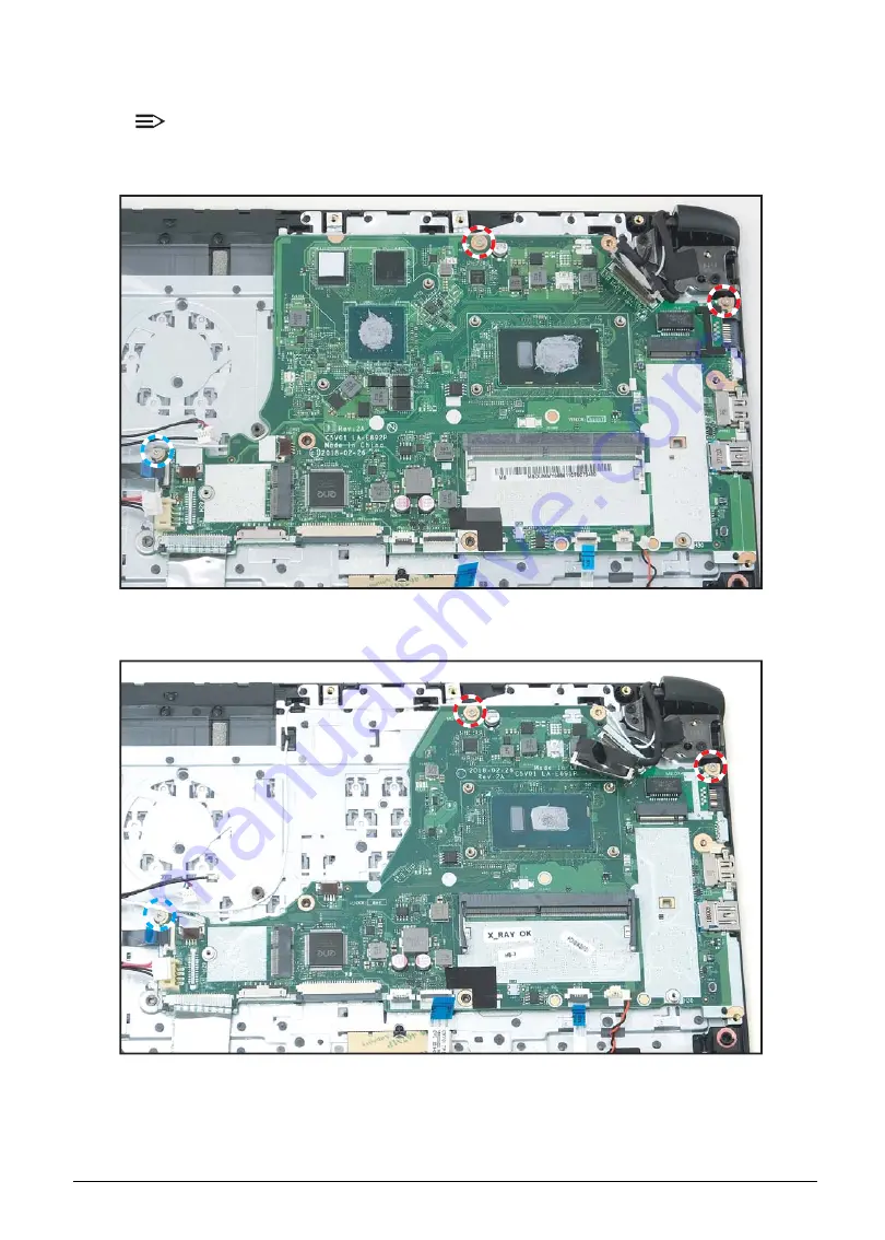
Attach the two (2) screws M 2.0 x 4.0 (marked with red-white circle) and the screw M 2.5 x 3.0
(marked with blue-white circle) to secure the mainboard to the upper case.
NOTE:
Screw torque force:
M 2.0 x 4.0 = 1.8~2.2kgf.cm
M 2.5 x 3.0 = 1.8~2.2kgf.cm
Figure 5-136. Securing the Screws (Discrete)
Figure 5-137. Securing the Screws (UMA)
Summary of Contents for A315-53G
Page 1: ...A315 53 A315 53G S E R V I C E G U I D E ...
Page 23: ...Hardware Specifications and Configurations 1 16 Figure 1 8 System Block Diagram Discrete ...
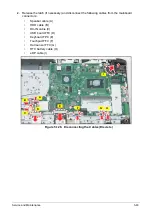
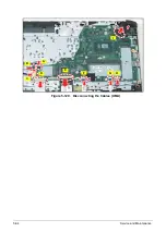
Page 224: ...5 84 Service and Maintenance Figure 5 129 Disconnecting the Cables UMA C A F D B E G H I ...
Page 230: ...5 90 Service and Maintenance Figure 5 139 Connecting the Cables UMA C A F D B E G H I ...
Page 301: ...CHAPTER 8 Online Support Information Online Support Information 8 2 Introduction 8 2 ...
Page 303: ......

