


Installation & Operation Manual - Model AVC4000
Contents of this Manual are Subject to Change Without Notification
Page 24
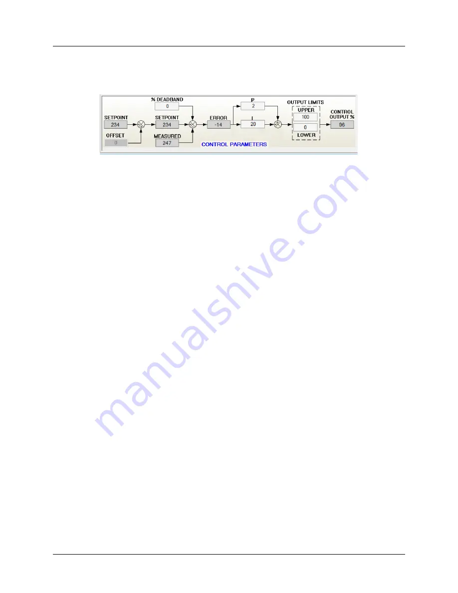
6.5.7 Control Parameters Diagram
The Control Diagram provides real-time information of the parameters associated with the
closed-loop control function. Configurable parameters are displayed in the white boxes and
non-configurable parameters are displayed in gray. Each parameter is briefly described below.
•
SETPOINT:
The SETPOINT value is based on the controller
“
Operating
Mode”
and is not a
configurable parameter in the CONTROL OBJECT. The Min and Max Volume Setpoint values
can be displayed by hovering the mouse over the SETPOINT box. The SETPOINT display box
will change to yellow when the calculated setpoint value is greater than the maximum or
less than the minimum allowable value.
•
OFFSET
: The OFFSET value is a configurable parameter which is normally used in tracking
pair applications. The sum of the OFFSET and SETPOINT make up the control loop SETPOINT
value. Polarity can be either positive or negative, based on application. The offset
parameter is disabled when operating in Fume Hood Mode.
•
% DEADBAND
: The % DEADBAND value is a configurable parameter which is applied as a
percentage of the SETPOINT value. The purpose of the DEADBAND is to improve control
loop stability by holding the control output constant until the ERROR exceeds the %
DEADBAND. The DEADBAND also serves to reduce the wear and tear on the actuator.
•
MEASURED:
The MEASURED value is the airflow measurement provided by the airflow
sensors and is not a configurable parameter. The airflow measurement value is the process
variable which closes the feedback loop.
•
ERROR:
The control ERROR is difference between the SETPOINT and MEASURED values.
The control ERROR is input to the PI algorithm which generates the control output.
•
P & I:
The AVC utilizes a parallel PI algorithm which includes two configurable parameters,
“
P
”
(Proportional Gain) and
“
I
”
(Integral). Both parameters act in parallel on the same error
and are combined to generate the control output signal. Increasing the
“
P
”
term makes the
control loop more sensitive and less stable. The
“
I
”
term, sometimes referred to as
“
automatic reset
”
, increases the control output by the integral of the error. Increasing the
“I” term makes the control loop more sensitive and less stable. Both the “P” and “I” terms
can vary based on the valve size and operating parameters. The factory default values for P
& I will accommodate the majority of applications.
•
OUTPUT LIMITS:
The control output limits are configurable parameters which are
essentially clamps for the control output. Normally the LOWER limit is set to 0% and the
UPPER limit is set to 100%. The OUTPUT LIMITS are only used for applications that would
benefit from limiting the control output thereby preventing the valve from fully closing
and/or fully opening.
•
CONTROL OUTPUT:
The CONTROL OUTPUT % is generated by the PI control loop and is
used to modulate the valve actuator resulting in a reduced error between the setpoint and
measurement.


