OPERATION
To adjust detail, press
DETAIL
then
UP
or
DOWN
until the sharpest display
is attained. Detail level should be roughly proportional to input signal quality. Higher
levels of detail improve good quality signals. Lower levels of detail reduce noise in poor
quality signals.
Color
1) The Color function is used to adjust color saturation levels when using the optional
Multi-standard Decoder.
To adjust color, press
COLOR
then
UP
or
DOWN
until the desired color saturation
level is displayed. If Color is set to a 0% level, the result will be a black and white
picture. If Color is set too high, the color levels in the picture will be over-powering.
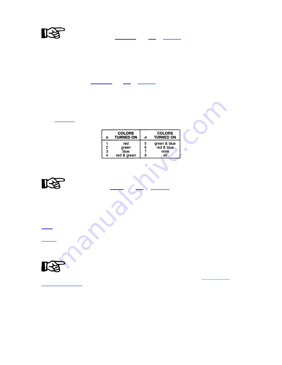
2) The Color function also allows you to turn on or off the red, green and/or blue color
components of the picture.
Press
COLOR
followed by a number
(n)
to select the color components you want turned
on. The chart shown here shows the selection variations.
Tint
The Tint function is used to adjust color hue to obtain true color reproduction of NTSC
signals when using the optional Multi-standard Decoder.
To adjust tint, press
TINT
then
UP
or
DOWN
until an optimum display is
attained. It is best to adjust tint while displaying an image with natural flesh tones.
Note: Tint is not adjustable for PAL or SECAM
video sources.
Picture Functions
>
Picture functions are accessed through the Picture menu. To display this menu, press
PIC
.
PIC 1
Phase
The Phase function is used to move the picture up, down, left, or right within the picture
display area.
To adjust phase, select Phase from the Picture menu. Two slidebars are
displayed: a Horizontal Phase sliders and a Vertical Phase sliders. Press
UP, DOWN
LEFT or RIGHT
to move the picture in the direction of the arrows so that the entire
picture is visible and centered.
Note: If the picture cannot be made entirely visible, an adjustment to blanking
or retrace
time may be required: refer to the blanking and retrace entries in
this section.
3-17
Summary of Contents for Model 8
Page 1: ......
Page 44: ...INSTALLATION SETUP Figure 2 29 ACON Installation Examples 2 38 ...
Page 104: ...Physical Dimensions 5 5 ...
Page 105: ...5 6 ...
Page 113: ...A p p e n d i x B B 1 ...
Page 114: ...B 2 ...
Page 115: ...C 1 ...
Page 116: ...C 2 ...
Page 117: ...D 1 ...
Page 118: ...D 2 ...
Page 119: ...E 1 ...
Page 120: ...F 1 ...
Page 121: ...F 2 ...
Page 122: ...F 3 ...
Page 123: ...F 4 ...
Page 124: ...F 5 ...
Page 125: ...F 6 ...
Page 126: ...F 7 ...
Page 127: ...F 8 ...
Page 128: ...F 9 ...
Page 129: ...F 10 ...
Page 130: ...G 1 ...
Page 131: ...Index 1 ...
Page 132: ...Index 2 ...


