18
Coolant Pressure Switch
This switch is located in the water piping at the inlet of the evaporator. It is designed to shut the unit down if there is
insufficient coolant pressure at the evaporator and hence coolant flow through the evaporator. The switch is adjustable;
however, no adjustments should be made without prior approval from the factory. If the chiller shuts down due to low
coolant flow, pressing the Start button on the control panel can restart it. This switch is disabled for 20 seconds after the
Start button is pressed so that the pump can develop adequate pressure to make the switch.
Automatic Water Make-Up (Optional)
With this option, a water supply can be connected to the chiller so that the water level in the reservoir is automatically
maintained. When the water level in the reservoir drops below the low level on the float switch, a solenoid valve will be
opened to allow fresh water into the system. When the water level reaches the high level on the float switch, the solenoid
valve is closed.
Note: This option is not normally recommended for systems that depend on a glycol solution to prevent freeze-ups. Automatic water make-up may
cause reduction of the glycol concentration, which may result in an evaporator freeze-up.
Upgraded Pumps (Optional)
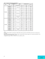
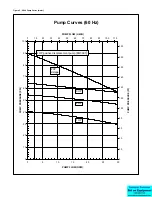
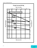
The standard pumps that have been selected for each size chiller will meet the requirements of most applications;
however, in certain instances, larger pumps may be required to provide the desired flow and pressure for a specific
application. The horsepower of the pump will be indicated on the chiller nameplate.
Preventive Maintenance
Once your portable chiller has been placed into service, the following maintenance procedures should be adhered to as
closely as possible. The importance of a properly established preventive maintenance program cannot be overemphasized.
Taking the time to follow these simple procedures will result in substantially reduced downtime, reduced repair costs, and
an extended useful lifetime for the chiller. Any monetary costs of implementing these procedures will almost always more
than pay for it.
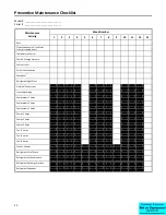
To make this as simple as possible, a checklist should be prepared which lists the recommended service operations and the
times at which they are to be performed. At the end of this section we have included a checklist that can be used for this
purpose. Notice that there are locations for voltage readings, amperages, etc. so that they can be monitored over time.
With this information, maintenance personnel may be able to correct a potential problem before it causes any downtime.
For best results, these readings should be taken with a full heat load from process, preferably with similar operating
conditions each time. The following is a list of suggested periodic maintenance.
Once a Week
1.
(Air Cooled Units Only) Check the surface of the air cooled condenser filter (if so equiped) and coil for dirt and debris.
To clean, rinse thoroughly with water. Mild detergent can be used to remove smoke and or grease stains.
2.
Check to make sure that the To Process temperature is maintained reasonably close to the Set Point temperature. If
the temperature varies more than 5°F (3°C) from the set point, there may be a problem with the chiller. If this is the
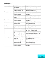
case, refer to the Troubleshooting Chart or contact the Customer Service Department.
3.
Check the pump discharge pressure on the gauge on the back panel of the chiller. Investigate further if the pressure
starts to stray away from the normal operating pressure.
4.
Check the coolant level in the reservoir. Replenish if necessary making sure to take proper precautions to maintain the
appropriate glycol concentration.
5.
Check coolant circulation pump for leaks in the seal area. Replace pump seal if necessary.
6.
Check refrigerant sight glass for air bubbles or moisture indication. If the sight glass indicates that there is a
refrigeration problem, have the unit serviced as soon as possible.
Once a Month
Repeat items 1 through 6 as listed above and continue with the following.


