background image


unsatisfactory chiller performance is poorly designed piping.  Avoid unnecessarily long lengths of hoses or quick disconnect 
fittings that offer high resistance to water flow.  When manifolds are required for water distribution, they should be 
installed as close to the use point as possible.  Provide flow-balancing valves at each machine to assure adequate water 
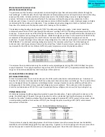
distribution in the entire system.  Typically when piping is overhead with a total run length over 25 feet (8 M) there should 
be a check valve in the supply line and an inverted P trap with a vacuum break valve installed as shown in Figure 1.  The 
height of the return line must not exceed 25 feet (8 M) when using an inverted P trap configuration.  If  a vertical rise 
greater than 25 feet (8 M) is required, a solenoid valve must be installed in the return line at the chiller instead of inverted P 
trap with vacuum break. 
 

Figure 1 - Recommended Overhead Piping 


Interconnecting Refrigerant Piping 

(EQR Models Only) The chiller unit is shipped with a nitrogen holding charge and has a full charge of oil, excluding the 
additional charge for field piping. Proper evacuation is required prior to charging with refrigerant.  The chiller is for use only 
with the air-cooled condenser provided with the unit. The following section covers the required piping between the chiller 
and the provided air-cooled condenser.


Caps are located on the discharge and liquid lines. These line sizes do not necessarily reflect the actual line sizes required 
for the piping between the chiller and the air-cooled condenser. The installing contractor need only provide the 
interconnecting piping between the chiller and the air-cooled condenser.


Refrigerant piping size and piping design has a significant effect on system performance and reliability. For specific pipe 
sizing and configuration, refer to the EQR Series Chiller Remote Air Cooled Condenser Installation Guidelines Manual. All 
piping should conform to the applicable local and state codes. Use refrigerant grade copper tubing only and isolate the 
refrigeration lines from building structures to prevent transfer of vibration. Do not use a saw to remove end caps. This 
might allow copper chips to contaminate the system. Use a tube cutter or heat to remove the caps. When sweating copper 
joints it is important to flow dry nitrogen through the system. This prevents scale formation. Do not use soft solders. For 
copper-to-copper joints use a phos-copper solder with 6% to 8% silver content. Use a high silver content brazing rod for 
copper-to-brass or copper-to-steel joints. Only use oxy-acetylene brazing. 


Start-Up 

 
Every unit is factory set to deliver chilled water in accordance with the standard operating specifications for that particular 
chiller.  Due to variables involved with different applications and different installations, minor adjustments may be required 
during the initial start-up to ensure proper operation.  The following start-up procedure should be followed in sequence.  If 
trouble is encountered during start-up, the fault can usually be traced to one of the control or safety devices.  This outline 
can be used as a checklist for the initial start-up and for subsequent start-ups if the chiller is taken out of service for a 
prolonged period of time. 
 

Summary of Contents for EQ Series

Page 1: ...Copyright Thermal Care Inc 2010 EQ Series Portable Chillers Installation Operation and Maintenance Manual ...

Page 2: ...roprocessor Control Fault Logic 7 Power 8 Start 8 Stop 8 Alarm Reset 8 Alarm Silence 8 Lower Set Point Temperature 8 Raise Set Point Temperature 8 No Flow 8 High Refrigerant Pressure 9 Low Refrigerant Pressure 9 Freezestat 9 Low Oil Pressure 9 Over Set Point 9 Under Set Point 9 Pump On 9 Compressor On 9 Partial Load 10 Water Make Up 10 Low Water Level 10 High Water Temperature 10 Probe Fault 10 Ch...

Page 3: ...ant Pump 17 Pressure Gauge 17 Y Strainer 17 High Refrigerant Pressure Switch 17 Low Refrigerant Pressure Switch 17 Freezestat 17 Coolant Pressure Switch 18 Automatic Water Make Up Optional 18 Upgraded Pumps Optional 18 Preventive Maintenance 18 Once a Week 18 Once a Month 18 Every Three Months 19 Preventive Maintenance Checklist 20 Troubleshooting 21 Charts and Drawings 23 Table 8 EQ Air Cooled Ch...

Page 4: ...nicians must be certified by an EPA approved organization It is recommended that good piping practices are followed and that the information in this manual is adhered to We cannot be held responsible for liabilities created by substandard piping methods and installation practices external to the chiller We trust your equipment will have a long and useful life If you should have any questions pleas...

Page 5: ...up for all three phase systems Operation of the compressor with incorrect electrical phase sequencing will result in mechanical damage to the compressors The phasing must be checked with a phase sequence meter prior to applying power The proper sequence should read ABC on the meter If the meter reads CBA open the main power disconnect and switch two line leads on the line power terminal blocks or ...

Page 6: ...24 C 3 11 3 3 8 14 3 GPM L min 80 F 27 C 4 2 15 9 5 4 20 4 GPM L min 85 F 29 C 6 4 24 2 8 2 31 GPM L min 90 F 32 C Call factory Call factory The minimum flows are determined using the condenser water regulating valve setting of 210 PSI 1 45 Mpa for a given supply temperature The supply temperature range is from 40 F 4 4 C to 90 F 32 C Supply temperatures beyond this range are not recommended and m...

Page 7: ... the air cooled condenser The installing contractor need only provide the interconnecting piping between the chiller and the air cooled condenser Refrigerant piping size and piping design has a significant effect on system performance and reliability For specific pipe sizing and configuration refer to the EQR Series Chiller Remote Air Cooled Condenser Installation Guidelines Manual All piping shou...

Page 8: ... connections are secure Open the cabinet and fill the chilled water reservoir with the proper water or water glycol solution See Table 4 for recommended glycol solutions 25 glycol is recommended even if running at temperatures higher than 25 F to help protect the evaporator from potential freezing Use glycol with a corrosion inhibitor only The external sight glass located at back of unit may also ...

Page 9: ...shed through the evaporator before the compressor can operate Under certain conditions the pressure loss in process lines may not be great enough to allow the pressure switch to close A process throttling valve must be installed to regulate process pressure if this condition appears 12 Set water flow through the evaporator as indicated in Table 3 A significant increase in flow beyond the recommend...

Page 10: ...ired2 Remote Alarm Activated3 No Flow LED Yes Yes No No Yes High Refrigerant Pressure LED Yes Yes Yes No Yes Low Refrigerant Pressure LED Yes No Yes No Yes Freezestat LED Yes No Yes Yes Yes Low Oil Pressure LED Yes Yes Yes Yes Yes Over Set Point LED No No No No Yes Under Set Point LED Yes No Yes No Yes Low Water Level LED No No No No No High Water Temperature LED No No No No No Probe Fault LED Yes...

Page 11: ...chased depressing the Alarm Silence button will disable the horn The horn will not reactivate until the alarm has been reset and a subsequent alarm has been triggered If the Remote Alarm contacts option has been purchased depressing the Alarm Silence button will open the contact that was closed when the alarm occurred The contact will not close again until the alarm has been reset and a subsequent...

Page 12: ...ops below the factory set level on the oil pressure switch the compressor and pump will shut off and the Low Oil Pressure LED will be illuminated In order to reset the Low Oil Pressure fault press the Alarm Reset button after resetting the mechanical pressure switch located inside of the cabinet near the compressor Over Set Point The Over Set Point LED will be illuminated if the To Process tempera...

Page 13: ...k has developed in the system If this occurs the Water Make Up LED turns off and the Low Water Level LED remains illuminated Low Water Level This LED is nonfunctional on standard units and will only be active if the Low Water Level option or the Water Make Up option has been purchased When the water level in the reservoir drops below the lower limit of the float switch the Low Water Level LED is i...

Page 14: ...nd release the Start button to store the new selection into the controller memory 6 Press and release the Power button once to exit the function Press and release the Power button again to restore controller power ...

Page 15: ... Data direction register failure Controller requires servicing Contact Manufacturer for repair or replacement 120 Communication data register failure Controller requires servicing Contact Manufacturer for repair or replacement 121 Timer data register failure Controller requires servicing Contact Manufacturer for repair or replacement 122 Hardware watchdog data register failure Controller requires ...

Page 16: ...ncludes an alarm horn that will be activated by certain faults Refer to Table 5 for the Microprocessor Control Fault Logic to determine which faults will trigger the Alarm Horn The Alarm Horn will be silenced by clearing the fault or by pressing the Alarm Silence button If this option is selected in conjunction with the remote control panel the Alarm Horn will be mounted on the chiller and not the...

Page 17: ... the coolant being delivered to the process is controlled by adjusting the amount of heat transferred in the evaporator After leaving the evaporator the coolant passes the Freezestat and thermocouple The Freezestat only on EQ2 series is a safety control that is connected to the microprocessor The thermocouple senses the temperature of the coolant being delivered to process and communicates this te...

Page 18: ...system may not be able to put enough of a load on the evaporator and the coolant temperature will begin to drop When the coolant temperature drops 7 F 3 C below the set point temperature the controller will shut the compressor off When the coolant temperature rises back to the set point temperature the compressor comes back on The compressor will remain off for at least two and one half minutes to...

Page 19: ...frigerant into the evaporator Superheat is the difference between the saturated evaporative temperature and the actual measured temperature at the TXV sensor bulb The superheat is factory set for 10 F to 12 F 5 C to 6 C and should never exceed 15 F 8 C Only a trained refrigeration technician should adjust this valve Refrigerant Sight Glass The refrigerant sight glass is located in the liquid line ...

Page 20: ...ld be installed external to the cabinet on the return from process line High Refrigerant Pressure Switch The High Refrigerant Pressure switch is designed to limit the compressor discharge pressure within the design parameters of the compressor The switch is located on the discharge side of the compressor and can be reset by first pressing the manual reset button located on the High Refrigerant Pre...

Page 21: ...substantially reduced downtime reduced repair costs and an extended useful lifetime for the chiller Any monetary costs of implementing these procedures will almost always more than pay for it To make this as simple as possible a checklist should be prepared which lists the recommended service operations and the times at which they are to be performed At the end of this section we have included a c...

Page 22: ...r fans or blowers on air cooled units and pump to confirm that they are drawing the proper current Every Three Months Repeat items 1 through 9 listed above and continue with the following 10 The Y strainer basket should be removed and cleaned if necessary This may be required more often if contaminants can easily get into the process water 11 Have a qualified refrigeration technician inspect the o...

Page 23: ...led units Temperature Control Pump Discharge Pressure Coolant Level Glycol Concentration Pump Seal Refrigerant Sight Glass Electrical Connections Incoming Voltage Compressor L1 Amps Compressor L2 Amps Compressor L3 Amps Pump L1 Amps Pump L2 Amps Pump L3 Amps Fan L1 Amps Fan L2 Amps Fan L3 Amps Clean Y Strainer Refrigerant Circuit Check Refrigerant Suction Pressure Refrigerant Discharge Pressure Re...

Page 24: ...on pressure sensor Check for proper range replace if faulty Microprocessor control board Replace if faulty High refrigerant pressure Dirty air filters air cooled units only Clean filters Air flow obstruction air cooled units only Make sure chiller is installed in accordance with recommendations in this manual High ambient air temperature air cooled units only Ambient temperature must be reduced be...

Page 25: ... Erratic temperature control Low coolant flow through evaporator Adjust flow to proper level Intermittent overloading of chiller capacity Check to make sure chiller is properly sized for process load Hot gas bypass valve Contact refrigeration service technician Microprocessor control board Replace if faulty Thermocouple Replace if faulty Insufficient cooling temperature continues to rise above set...

Page 26: ... 4 3 3 7 0 8 0 11 10 9 EQ2A03 208 3 60 12 6 1 745 kW 3 9 372 kW single phase 3 0 0 24 23 6 230 3 60 11 4 3 6 2 9 0 22 21 5 460 3 60 6 2 1 8 1 5 0 11 11 9 208 3 60 12 6 2 1 49 kW 7 5 3 0 0 24 27 3 230 3 60 11 4 6 8 2 9 0 22 25 0 460 3 60 6 2 3 4 1 5 0 11 13 7 208 3 60 12 6 3 2 24 kW 10 6 3 0 0 24 30 4 230 3 60 11 4 9 6 2 9 0 22 27 8 460 3 60 6 2 4 8 1 5 0 11 15 1 208 3 60 12 6 2 1 49 kW 2 stg 8 8 3...

Page 27: ...30 3 60 11 4 3 6 0 22 18 9 460 3 60 6 2 1 8 0 11 10 6 208 3 60 12 6 2 1 49 kW 7 5 0 24 24 3 230 3 60 11 4 6 8 0 22 22 1 460 3 60 6 2 3 4 0 11 12 2 208 3 60 12 6 3 2 24 kW 10 6 0 24 27 4 230 3 60 11 4 9 6 0 22 24 9 460 3 60 6 2 4 8 0 11 13 6 208 3 60 12 6 2 1 49 kW 2 stg 8 8 0 24 25 6 230 3 60 11 4 8 0 22 23 3 460 3 60 6 2 3 7 0 11 12 5 Notes RLA Rated Load Amps based on a percentage of the MMTC Ma...

Page 28: ...0 20 30 40 50 60 70 80 90 100 0 5 10 15 20 25 30 PUMP FLOW GPM PUMP PRESSURE PSI 0 20 40 60 80 100 120 140 160 180 200 220 0 10 20 30 40 50 60 70 80 90 100 110 PUMP FLOW L MIN PUMP PRESSURE FT HP positive discplacement pump EQ3A01 2 HP 2 stage 3 HP 2 HP 1 HP ...

Page 29: ...er Pump Curves 50 Hz 0 10 20 30 40 50 60 70 0 5 10 15 20 25 PUMP FLOW GPM PUMP PRESSURE PSI 0 20 40 60 80 100 120 140 160 0 20 40 60 80 PUMP FLOW L MIN PUMP PRESSURE FT HP positive discplacement pump EQ3A01 2 HP 2 stage 3 HP 2 HP 1 HP ...

Reviews: