17
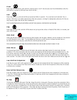
microprocessor controller controls the amount of hot gas used. Eliminating cycling of the compressor is extremely
desirable as it significantly extends its lifetime expectancy.
Reservoir
The reservoir is mounted to the inside of the cabinet. The reservoir is made of polyethylene and is fully insulated. A sight
glass is included so the coolant level can be observed from the back of the chiller. The sight glass can also be used to fill or
drain the reservoir. There is also a removable cover on the top of the reservoir. During chiller operation the reservoir
should be at least half full. For most installations the reservoir has sufficient capacity to handle coolant drain back from the
process equipment which occurs during chiller shut down. For installations with overhead piping runs of over 25 feet (8 M)
special precautions will have to be made during installation (see Installation Section, Diagram 1).
Note: The reservoir cannot be pressurized. Modifications to the chiller that would result in pressurization of the reservoir will void the warranty.
Coolant Pump
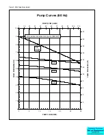
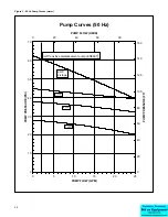
The EQ3A01 is equipped with a close coupled postive displacement rotary vein pump while the other models are equipped
with a close-coupled centrifugal pump. All pumps have a mechanical seal and are constructed of nonferrous material. The
pump is factory tested for the specified operating conditions. The pump motor meets NEMA specifications and industry
standards.
Pressure Gauge
A pressure gauge is mounted on the back panel of the chiller. This gauge displays the pressure of the coolant at the
discharge of the pump. It can be used to determine the approximate point on the pump curve in which the pump is
operating.
Y-Strainer
A Y-strainer with a 20-mesh screen is installed in the water line on EQ2 series chillers to help protect the evaporator
passages from becoming clogged. This strainer is shipped loose on EQ3A01 and should be installed external to the cabinet
on the return from process line.
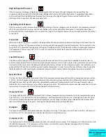
High Refrigerant Pressure Switch
The High Refrigerant Pressure switch is designed to limit the compressor discharge pressure within the design parameters
of the compressor. The switch is located on the discharge side of the compressor and can be reset by first pressing the
manual reset button located on the High Refrigerant Pressure safety switch and then by pressing the Alarm Reset button on
the control panel. The setting on this switch is set to cut out at 375 PSIG (2.59 MPa) for air cooled units or 300 PSIG (2.07
MPa) for water cooled units.
Low Refrigerant Pressure Switch
The Low Refrigerant Pressure switch is designed to limit the compressor suction pressure to within the designed
parameters of the compressor. The switch is located in the suction side of the compressor and can be reset by pressing the
Alarm Reset button on the control panel. The setting on this switch is set to cut out at 10 PSIG (69 kPa) and cut in at 40
PSIG (276 kPa) for EQ3A01. On all other models the switch is set to cut out at 25 PSIG (172 kPa) and cut in at 55 PSIG (379
kPa).
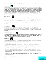
Freezestat
(EQ2 series only) The freezestat control is an electronic thermostat that senses the coolant temperature separately from
the microprocessor controller. This safety is designed to limit the temperature of the coolant leaving the evaporator and
prevent possible freeze-up situations. This control should be set 10°F (5°C) below the minimum coolant supply
temperature, and there should be a sufficient glycol concentration for 10°F (5°C) below the freezestat setting.
Note: It is critical that the freezestat is set properly and that there is sufficient glycol in the system to correspond with the freezestat setting. Freeze-
ups can cause extensive damage to several components in the chiller, and the warranty does not cover repairs required due to a freeze-up.
The Freezestat is located inside the main electrical enclosure. If the chiller shuts down due to the Freezestat, the Alarm
Reset button on the control panel must be pressed before the chiller can be restarted.

