page 8
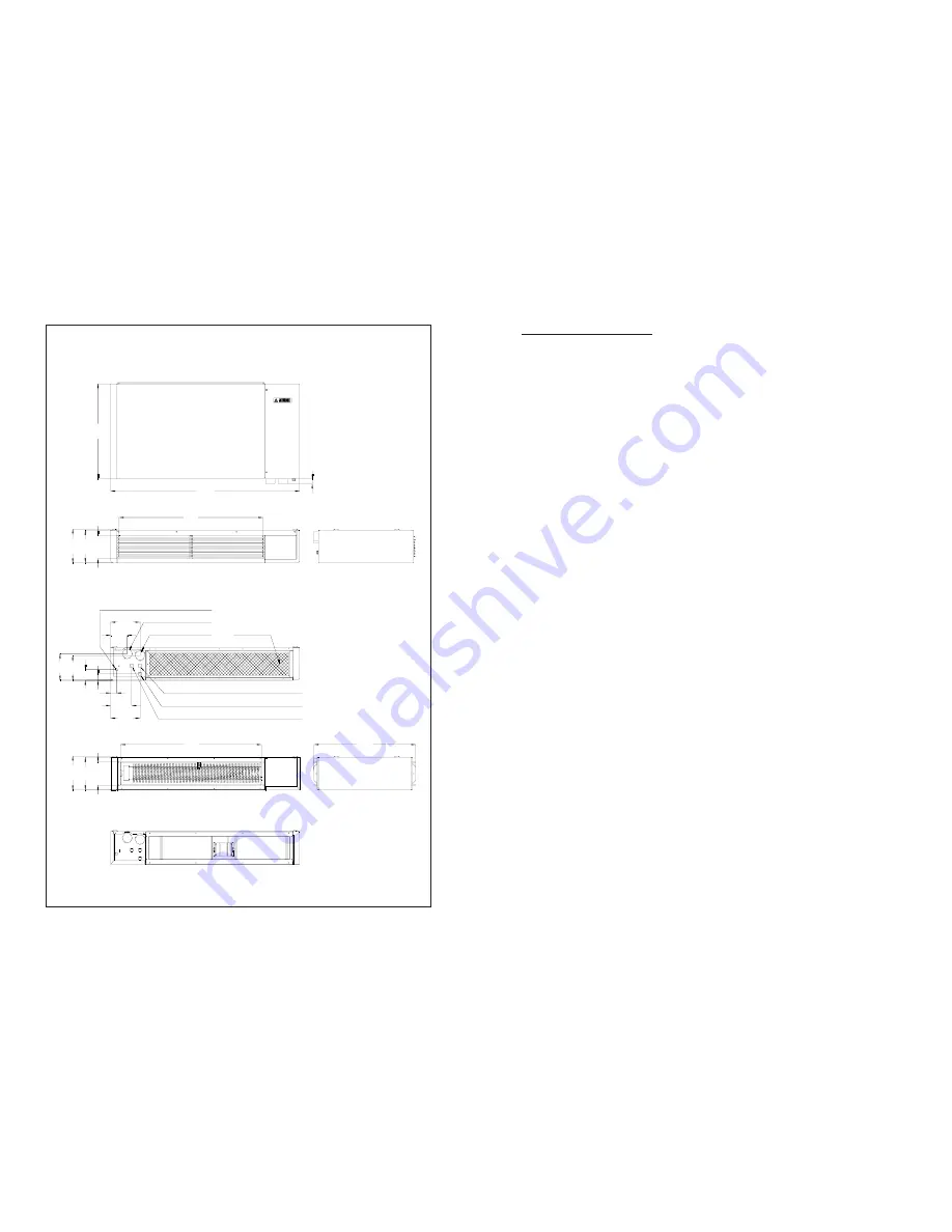
Fig. 1
219
1.220
613
32
212
151
930
38
171
160
69
40
136
190
910
219
212
150
657
1.10 DIMENSIONS - WR and WD versions for ceiling installation
Bottom view of
the WR version
Front view of the WR version
Front view of the WD version
Side view of the WR version
Side view of the WD version
Rear view of the WR version
Rear view of the WD version
ISO 228/1 G1/2”A gas connection
Air intake, Ø 60
190
108
Flue gas discharge, Ø 60
Air filter
Optional timer cable outlet
Electric power supply cable inlet
Control panel cable outlet
page 29
7. OPERATING DEFECTS
7.1 PRELIMINARY TESTS
Before performing specific tests, make sure that:
a) The electric power supply is properly connected
(pay particular attention to the phase-neutral
polarity and ground connector) and that any
external adjustment components (for example,
the programmable timer) function correctly.
b) The gas supply is correct, the gas on-off valve
is open, and the pressure to the burner
corresponds to what is indicated in the
technical data table.
c) The external terminals of the combustion air
intake duct and the combustion product
exhaust flue are not obstructed and that the
material they are made of has not deteriorated.
d) The control panel functions correctly.
7.2 POSSIBLE DEFECTS
The following is a list of possible defects along
with their probable causes. The information
indicated in italics refers to repair operations or
corrections which are the responsibility of the
authorised Technical Service Centre.
7.2.1 The appliance does not start even if the
conditions described in the previous
points are correct.
a) the flame detection circuit of the control
equipment is malfunctioning and the initial self-
check does not allow the cycle to continue.
-
Replace the control equipment (see point
8.1).
b) The flame detection electrode has an earth
leakage.
-
Check the correct position of the electrode.
The ceramic insulation material may be
cracked and this is difficult to determine
visually. In case of doubt, replace the electrode
(see point 8.7).
c) The differential pressure switch’s contacts
are frozen in the position they assume when
the draft is correct.
-
Change the pressure switch if its microswitch
does not reset the contacts to the proper
position (see point 8.4).
d) The flue gas expeller fan’s motor has failed
and the differential pressure switch will not
allow startup to proceed.
-
Change the fan. Be careful to reassemble the
unit as shown in figure 31 (see point 8.8).
7.2.2 The control equipment does not shut
down, but the cycle remains in a
continuous preventilation phase
a) The differential pressure switch will not allow
startup to proceed because the flue gas
exhaust flue or the air supply duct is
obstructed.
-
First eliminate any obstructions from the
terminals. In any case check the entire path of
the ducts for damage or alterations.
b) The differential pressure switch will allow
startup to proceed because the flue gas
expeller fan does not function correctly and
does not develop enough suction.
-
Check to see if there are any problems of
wear with the rotation of the fan motor. Make
sure that the fan is positioned correctly, that
there is nothing that interferes with the rotation,
and that there are not any deformations. If
necessary, change the fan. Be careful to
reassemble the unit as shown in figure 31
(see point 8.8).
c) The differential pressure switch will not allow
startup to proceed because it is broken or its
electrical connection has been interrupted.
-
Check that the connection cable and the
corresponding terminals are in good condition.
Do not attempt to adjust the pressure switch
by removing the seal; instead, change it.
d) The differential pressure switch will not allow
startup to proceed because the pressure inlet
tube is obstructed or the silicone connection
tube is disconnected or broken.
-
Make sure that the silicone tube is connected
correctly and that it does not have any holes
or cuts in it. If it is not damaged, check the
steel pressure inlet tube and remove any
obstructions or deposits from it. It will be
necessary to access the inside of the
exchanger’s flue gas collector to completely
carry out this operation.
7.2.3 At the end of the preventilation phase,
the ignition electrodes do not discharge
and the control equipment shuts down
within the safety time
a) The ignition transformer is malfunctioning.
-
Replace the controller which contains the
transformer. Because these are electronic
components, it is advisable not to attempt to
replace just the transformer, especially if you
do not use the proper tools.
Summary of Contents for W
Page 2: ......


