35
1
2
3
4
5
9 - SECTION D
SOLAR STATION UNIT 2 PLUS
HUB RADIATOR PLUS 250 - 400 SOLAR
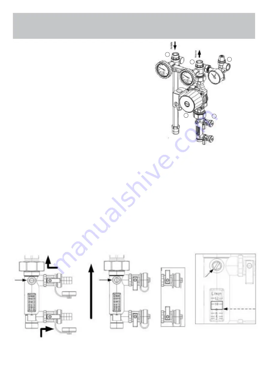
9.1 MAIN PARTS OF THE COMBINED CIRCULATION
GROUP FOR SYSTEMS SOLARI UNIT 2 PLUS
Round trip system
1 Ball valve on the delivery branch
(Thermometer with red ring and scale 0-120 °C)
with VNR (non-return valve) “Solar”
2 Ball valve on the return branch
(Thermometer with blue ring and scale 0-120
°C) with VNR (non-return valve) “Solar”
The “Solar” non-return valve inserted in the ball valve both on the
flow and return branches guarantees tightness and low pressure
drops.
To exclude the non-return valve, for example in case of system
emptying, turn the knob 45° clockwise.
Circulator
3 Manually adjustable 3-speed circulator.
Thanks to the tightness of the ball valves upstream and
downstream of the circulator, it can be removed without
emptying the system.
Security group
4 The CE and TUV certified safety safety group protects the
system from overpressures. It is calibrated at 6 bar beyond
which the group intervenes, and is also equipped with a
pressure gauge and connection to the expansion tank via an
optional 3/4 “flexible kit
Flow regulator
5 The regulator allows you to adapt the flow rate to your needs
of the system through a 3-way ball valve.
When the valve is in the closed position, normal circulation is
interrupted and it is possible to use the side tap to load the
system. There is a second side tap for draining. The proximity
of the 2 taps facilitates operations by minimizing the section
between loading and unloading.
The flow rate is indicated by the appropriate sliding cursor:
the feedback is immediate thanks to the proximity to the
regulating valve
9.2 Instructions for using the flow regulator when loading the system
(1)
Loading operations on the system:
Remove the cap from the side valves
and insert the hose holder.
Close the ball valve and open the side
loading and unloading valves.
Locking knobs of
loading / unloading;
Unscrew the fixing screw,
pull out the knob
and reinsert it rotated
of 180°
(2)
System commissioning:
Open the ball valve and close the side loading and unloading
valves. Remove the hose no longer used and screw the caps
back on.
To avoid accidental opening of the side taps, it is advisable to lock
the knobs in the closed position as shown on the side.
(3)
Adjust the flow rate by acting on the adjustment rod until the
desired flow rate is reached.
(NB)
the flow rate is indicated by pressing the lower profile of the
sliding cursor as a reference (see figure).
Discharge
Circulation
Load
valve
ball
closed
valve
ball
open
Adjustment
scope
Range indicated
in this example
8l / min


