Chapter 3: Option Selection
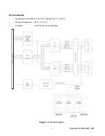
Refer to the setup programs provided with the board. Also, refer to the Block Diagram and the board
when reading this section of the manual.
There are seven jumpers that select the IRQ level, six jumpers that select the base address, two
jumpers that control the interrupt signals from the two I/O groups, and one jumper that affects the I/O
buffers’ output-enable (tristate) for both I/O groups.
External interrupts are accepted on the I/O connector(s) at pin 9 (bit C3). The interrupt occurs on the
rising edge of the signal. Interrupts are always enabled if the jumper is installed in the IEN position,
enabled if Port C bit 7 is low and the jumper is in the INP position, or disabled if the jumper is off the
posts. Interrupts are directed to levels #2 through #7 and #10 through #12 by jumpers installed at
locations labeled IRQ2 through IRQ7 and IRQ10 through IRQ12. Interrupts are enabled by writing any
value to base a Bh and disabled by reading from that address. Once an interrupt has occured it
must be cleared (by writing any value to base a Fh) for the next interrupt to occur. A jumper
must be installed in either the IEN or the INP position for the interrupt to function.
The 74LS245 input/output buffers can be enabled or disabled under program control. When the jumper
is in the BEN (Buffer Enable) position, the I/O buffers are always enabled. When the jumper is in the
TST (Tristate) position, the enabled/disabled state is controlled by a register. (See the programming
section of this manual for a description.) In either case, the buffers’ directions are automatically
configured by hardware that snoops the PPI command byte.
The Counter/Timer shares the same I/O space as the digital I/O Group 0. To ‘map in’ the
Counter/Timer, write any value to base a Dh. After programming the counters, read base
a Dh to ‘map out’ the counters and re-enable access to the DIO. This trick halves the I/O space
required by the board.
Manual 104-DIO-48E, 24E
10


