AC Tech Lenze MotionView OnBoard Communications Interface Reference Manual Download Page 19

1

P94DVN01A

Cyclic Data Access

5.1.1  Byte 0 – Control Word

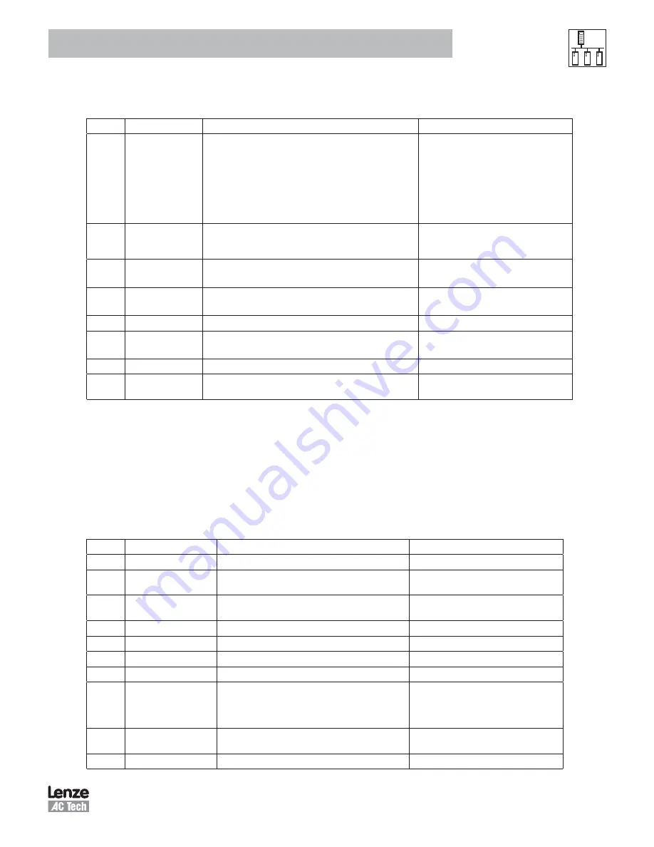
Table 8: Ouput Assembly - Control Word

Bit

Name

Description

Note

7

Enable

0 – disable drive
1 – enable drive

This bit controls PID 52
The Enable bit takes precedence over the 
rest of the command bits and the command 
type. If the drive is disabled (Enable bit = 
0) no motion command can be executed 
and the move command will be ignored. 
The response assembly will be issued as 
requested.

6

Reg Arm

The change from 0 to 1 arms the registration input C1

It is equivalent to the REGISTRATION ON 
language statement. (Internally this is the 
RegistrationOn function).

5

Hard Stop

1 – The drive stops the motion quickly
using the QDECEL and QACCEL values.

This bit controls PID 136 and sets it to 2

4

Smooth Stop

1 – The drive stops motion
using the normal DECEL and ACCEL values.

This bit controls PID 136 and sets it to 1

3

NA

0 – default setting (bit not used)

2

Relative

1 – Relative motion will be executed.
0 – Absolute motion will be executed

1

NA (0)

0 – default setting (bit not used)

0

Start Motion

Change from 0 to 1 starts a motion command equivalent to the 
MOVED or MOVEP language commands

This bit in combination with the Relative bit 
controls PID’s 92 and 93.

5.1.2  Byte 2 - Command Type

Command Axis (bits 7 to 5)

The values of these bits should always be 001 since the PositionServo has only 1 axis per drive.

Command Assembly Type

The Command Assembly Type ranges from 0x0 to 0x9 as listed in Table 9.

Table 9: Command Assembly Type

Type

Command

Description

Note

0x0

NOP

0x1

Start Trapezoidal Move

Initiates trapezoidal motion

Should be used together with the Start Motion
and Relative control bits

0x2

Set Target Reference

Sets the target reference PID 139 (IREF)

Target reference in RPS for velocity mode and 
in phase Amps (RMS) for current mode.

0x3

Set Acceleration

Sets the acceleration PID 181 (ACCEL)

0x4

Set Deceleration

Sets the deceleration PID 182 (DECEL)

0x5

Set Maximum Velocity

Sets the maximum profile velocity PID 180 (MAXVEL)

0x6

Set Quick Deceleration

Sets the quick deceleration PID 183 (QDECEL)

0x7

Set Velocity Profile

Sets the velocity for profiled velocity mode PID 185 (VEL)

Profiled velocity is the special operation of 
Position mode. To set profiled velocity mode 
set PID 138 to 1. To return back to normal 
positioning mode set PID 138 to 0.

0x8

Start S-curved Move

Initiates S-curve motion

Should be used together with the Start Motion 
and Relative control bits

0x9

Set User Variable V0

Sets PID 100 (V0)

Summary of Contents for Lenze MotionView OnBoard

Page 1: ...PositionServo DeviceNet Communications Module Communications Interface Reference Guide...

Page 2: ...commitment to update or to keep current the information in this manual MotionView PositionServo and all related indicia are either registered trademarks or trademarks of Lenze AG in the United States...

Page 3: ...le Types 5 3 3 2 Network Limitations 5 3 3 3 Connections and Shielding 6 3 3 4 Network Termination 6 4 Configuring Drive for DeviceNet Communication 8 4 1 Connect to the Drive with MotionView OnBoard...

Page 4: ...1 Data Scale Factor 17 5 2 3 Byte 2 Status Byte 2 17 5 2 4 Byte 3 Response Type 18 5 2 5 Bytes 4 through 7 Data 18 6 Explicit Messaging 19 6 1 Objects 64h and 65h 19 6 2 Example Explicit Message 19 7...

Page 5: ...ation includes information on compliance with the EN 61000 3 2 When installing the drive controllers in machines commissioning i e the starting of operation as directed is prohibited until it is prove...

Page 6: ...apt the controller to his application as described in the documentation DANGER After the controller has been disconnected from the supply voltage do not touch the live components and power connection...

Page 7: ...bined with it s efficient data formatting permit the coordination and control of multi node applications 2 2 Module Specification Group 2 Server Device Supported baudrates 125kbps 250kbps 500kbps Supp...

Page 8: ...d replace screws as illustrated in Figure 2 S921a Figure 2 Installation of DeviceNet Communications Module 3 2 DeviceNet Terminal Block Table 2 and Figure 3 illustrate the pinout of the PositionServo...

Page 9: ...rs that must be taken into consideration when designing a DeviceNet network For full details refer to the official DeviceNet Planning and Installation Manual available on the http www ovda org website...

Page 10: ...5 Connect to cubical panel earth as close to the drive as possible Figure 4a Network Daisy Chain Connection Figure 4b Ground Connection of Network Center Node 3 3 4 Network Termination In high speed f...

Page 11: ...94DVN01A Installation DeviceNet Master PositionServo DeviceNet Slave PositionServo DeviceNet Slave H L 120 120 DeviceNet Network DeviceNet Network H L H L Power Supply Figure 6 DeviceNet Network Wirin...

Page 12: ...screen is displayed Click Run to enter the MotionView program Once MotionView has launched verify motor is safe to operate click YES I have then select Connect from the Main toolbar top left The Conn...

Page 13: ...s CAN ID This parameter takes effect after the drive has been re booted power cycled Note DeviceNet valid addresses 0 63 CAN Boot Up Mode Pre Operational Operational or Pseudo Master modes are availab...

Page 14: ...10 REBOOT Message This can be done by cycling the power to the drive 4 2 2 Set CAN Parameters The CAN folder contains the configuration parameters for the CAN interface To change a CAN parameter use...

Page 15: ...ined value or click in the box adjacent to the parameter and enter a numeric value that is within the parameter s specified range Table 5 lists the range and default value for each CANOpen parameter T...

Page 16: ...Parameters All standard CAN parameters are reused by DeviceNet To enable DeviceNet functionality set variable 238 VAR_CAN_ENABLE_EPM 3 Variable 276 DNET_SCALE_POLL_IO is a new parameter that determin...

Page 17: ...t Codes can be found in the drive s user manual S94PM01 The DFAULT parameter PID 9 indicates the last drive fault In addition a new error code 43 is introduced to indicate a problem in the DeviceNet P...

Page 18: ...eger 32 bit data values scaled by the value of the 10 DNET_ SCALE_POLL_IO NOTE The Enable bit takes precedence over the rest of the command bits and the command type If the drive is disabled Enable bi...

Page 19: ...is bit in combination with the Relative bit controls PID s 92 and 93 5 1 2 Byte 2 Command Type Command Axis bits 7 to 5 The values of these bits should always be 001 since the PositionServo has only 1...

Page 20: ...he lowest byte first and the highest byte last Said another way in little endian format the least significant byte is stored at the lowest address Endian Format 16 bit Value 32 bit Value Byte Order Wo...

Page 21: ...ed I O command message is detected 2 In Position 1 motion complete and target position is within specified limits Bit 5 of the drive status PID 54 1 NA 0 0 default setting bit not used 0 In Motion 1 I...

Page 22: ...101 V1 0x14 Command Response Error This response is returned if any fault occurs or the last sent command is unsupported In this case byte 6 of the response assembly has copy of the command message by...

Page 23: ...cess As an example writing to variable VAR_ENABLE ID 52 a non 0 value will enable the drive Writing the same variable with a 0 zero value will disable the drive Another example could be writing the va...

Page 24: ...never its state changes or at a base heartbeat rate Cyclic Device will produce data at a defined interval EDS Electronic Data Sheet Explicit Message Contains module vendor information sent via a high...

Page 25: ...4 2 3 Set CANOpen Parameters PID237 CAN Bootup Delay 5 s R W 4 2 3 Set CANOpen Parameters PID238 CAN Enable 3 for DeviceNet R W 4 3 Configuration Parameters PID276 DeviceNet Poll I O Scaling 101 10 R...

Page 26: ...AC Technology Corporation 630 Douglas Street Uxbridge MA 01569 Telephone 508 278 9100 Facsimile 508 278 7873 www lenze actech com P94DVN01A...

Reviews: