User manual Version 1.0
Modbus Gateway
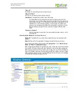
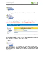
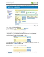
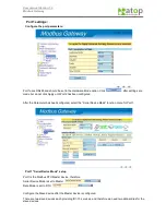
“Slave IP”
:
IP address for connecting to remote slave device.
“Slave TCP Port”
:
TCP port for connecting to remote slave device.
“Data Mode”
: Includes RTU, ASCII, and TCP modes.
The “Data Mode” here configures the communication protocol for the
slave device, and must be set to the communication protocol used by the
remote Ethernet-slave. The “Data Mode” listed here is independent to the
“Data Mode” in the Port-mode setting. In other words, the master and
slave can be configured with different communication protocols, and the
Modbus Gateway will perform the conversion between different data
types.
“Response Timeout”
:
Sets the response timeout from the remote Ethernet-slave device, unit in
microsecond.
ID routing table: Master ID
and
Slave ID
modes.
Master ID
: The Master ID is a virtual ID and each field must not duplicate with
another.
Slave ID
: Slave ID is the applicable ID range provided for the slave device.
The concept is identical to the setup for “
ID routing table
” in the
“Serial Device
Mode” as “Slave” configuration page
.
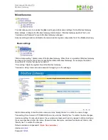
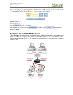
After configuring the Master ID and Slave ID, click “Add ID Set” to add to the buffer,
then confirm the range of Slave ID click “Add Set” to add to the Slave-setting list.
After all slave devices for the port have been configured, click “Commit Setting” to
save to the Modbus Gateway. To immediately apply the changes, click the “Apply”
button as below; otherwise, the “Commit Setting” button will only save the settings
to the Modbus Gateway configuration file.


