background image

User manual Version 1.0 
Modbus Gateway 


Network Settings 

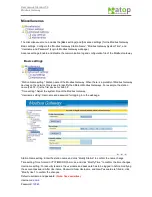
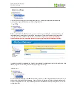
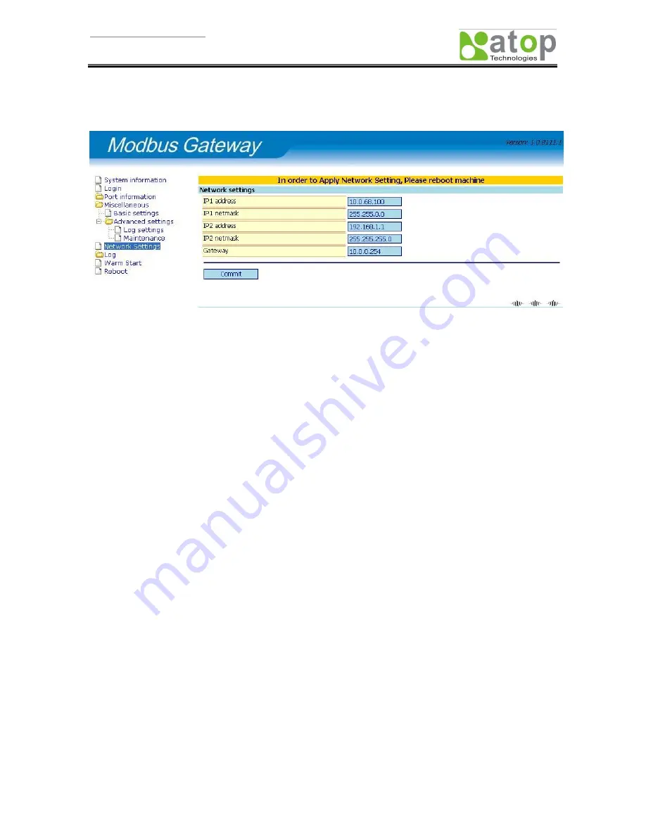
The Modbus Gateway features two network devices that can be configured. After carefully configuring the 
network settings, apply the changes or reboot to put into effect.   


Enter the LAN1 and LAN2 settings. If there are no Gateways on the same network as the Modbus Gateway, 
it is possible to use the current IP as the Gateway IP address.   

For example, when LAN1 is connected to the network with IP address 192.168.100.201 and there are no 
Gateways on the network, then the Gateway IP address can be configured with 192.168.100.201.   

Summary of Contents for ABLELink MB5000 Series

Page 1: ...ABLELink Modbus Gateway MB5000 Series User s Manual Version 1 1 Updated in March 2010 TEL 886 3 5508137 FAX 886 3 5508131 http www atop com tw...

Page 2: ...itions DC 8 Ethernet Port Pin Definitions RJ45 8 Serial Port Pin Definitions 9 2 Port and 4 Port Pin Definitions DB9 9 Configuration and Management 10 Connecting to the Setup Page 10 System informatio...

Page 3: ...meters 29 Port1 Serial Device Mode setup 30 Port2 settings 31 Configure the port parameters 31 Port2 Serial Device Mode setup 32 Example 2 Serial Port to Master Device 33 Port1 settings 34 Configure t...

Page 4: ...modify the hardware interface to use and easily switch to the existing hardware communication infrastructure Switching between Modbus Protocols Modbus Gateway supports the standard Modbus protocol and...

Page 5: ...e webpage setup for RS232 RS485 RS422 Effortlessly convert between Modbus TCP Modbus RTU and Modbus ASCII Hardware connections through serial and Ethernet ports for even easier integration No software...

Page 6: ...t Baud Rate 110bps 921Kbps Parity None Odd Even Mark Space Data Bits 5 6 7 8 Stop Bits 1 2 Flow Control None Software Xon Xoff Hardware RTS CTS Protection 15KV ESD 15KV ESD Connector 9 pin D Sub 9 pin...

Page 7: ...User manual Version 1 0 Modbus Gateway Hardware Diagram Diagram 2 Port Hardware Diagram 4 Port Hardware Diagram...

Page 8: ...User manual Version 1 0 Modbus Gateway Pin Definitions Power Pin Definitions 2 Port Power Pin Definitions DC DC 9V DC 30V Ethernet Port Pin Definitions RJ45 Pin Signal 1 TX 2 TX 3 RX 4 5 6 RX 7 8...

Page 9: ...nitions 2 Port and 4 Port Pin Definitions DB9 RS 232 RS 422 RS 485 Pin Signal Pin Signal Pin Signal 1 DCD 1 NC 1 NC 2 RXD 2 TXDB 2 NC 3 TXD 3 RXDB 3 DataB 4 DTR 4 NC 4 NC 5 GND 5 GND 5 GND 6 DSR 6 NC...

Page 10: ...evicevw EXE and directly select the IP address then Click the Browser button The software tool will use the default browser to open the setup page The second method is to launch the browser and then e...

Page 11: ...Station Name Name of this Modbus Gateway Model Name Model Name of this Modbus Gateway Serial No Serial Number of this Modbus Gateway Firmware version Version of this Modbus Gateway LAN1 IP Netmask of...

Page 12: ...logged in To make modifications to the Modbus Gateway the user must first login beforehand or at the system prompt after modifications are made Any modifications made will only be saved after the use...

Page 13: ...ing Port overview and Port information Port overview Port overview will list the current settings of all ports on Modbus Gateway while some detailed port information will not be displayed here and is...

Page 14: ...pply on the webpage after changes are made 2 Click the Warm Start function menu to the left 3 Click the Reboot function menu to the left 4 Cutoff the power and then recover the power After entering th...

Page 15: ...Serial Device Mode the above mentioned contents will differ 1 Port mode setting There are three options for the port Serial Device Mode Data Mode and Response Timeout Serial Device Mode Includes Mast...

Page 16: ...e settings Gateway TCP Port Network and Netmask and Data Mode Gateway TCP Port Modbus Gateway provides client connection to activate the TCP Port service Network and Netmask Combination of Network and...

Page 17: ...ster ID 1 10 corresponds to Slave ID 1 10 Master ID 11 20 corresponds to Slave ID 11 20 and Master ID 21 30 corresponds to Slave ID 21 30 When master sends the request for ID 1 11 and 21 the Modbus Ga...

Page 18: ...ocol will be configured based on the device connected to the port For example Port1 connected device uses the Modbus RTU communication protocol then Data Mode will be set to RTU vise versa if the conn...

Page 19: ...response timeout from the remote Ethernet slave device unit in microsecond ID routing table Master ID and Slave ID modes Master ID The Master ID is a virtual ID and each field must not duplicate with...

Page 20: ...to identify the different Modbus Gateways For example the station name Fab 3F 1 is the first device for Fab 3F Time setting Adjust the system time of the Modbus Gateway Username setting Username and...

Page 21: ...e the communication logs It is recommended that the communication log only be enabled during non online use for testing and debug purposes To enable the function checkmark the Record option and set th...

Page 22: ...Import Setting Click Browse and select the configuration file to recover the Modbus Gateway then click Export Setting Right click on Export Settings and then select Save target as in IE Enter the file...

Page 23: ...anges or reboot to put into effect Enter the LAN1 and LAN2 settings If there are no Gateways on the same network as the Modbus Gateway it is possible to use the current IP as the Gateway IP address Fo...

Page 24: ...n including both normal message and warn message The connection records of the client and Modbus Gateway will be logged in the warn message category The Warn message option has to be checked to log th...

Page 25: ...eld e g 192 168 100 31 12 and because a single IP may have multiple connections each connection will be identified with an ID in the brackets This ID can be looked up from the warn message in System l...

Page 26: ...d in Hex and finally the text string in brackets is the source of the data stream indicating that this entry is written to Port1 and the data source is 192 168 100 31 connection ID is 12 or the direct...

Page 27: ...on 1 0 Modbus Gateway Warm Start Warm Start is rebooting the Modbus Gateway without cutting off the power The Reboot option or cutting off the power then re powering should be used after modifying the...

Page 28: ...User manual Version 1 0 Modbus Gateway Reboot Reboot the Modbus Gateway system and all modified settings will be applied after the reboot...

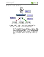
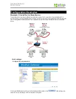
Page 29: ...devices with ID 1 10 using RS485 communication and Port2 connects 10 serial Modbus ASCII devices with ID 1 10 using RS422 communication Two computers are used to access the Master device as indicated...

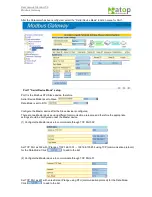
Page 30: ...e two Master devices using different communication protocols and therefore the appropriate settings should be configured under the Master device 1 Configure the Master device to communicate through TC...

Page 31: ...routed to Port1 and Master ID11 20 is routed to Port2 Port1 settings are as below Enter Master ID 1 10 Enter Slave ID 1 10 Click to add to the ID list After all settings are configured click but do n...

Page 32: ...are two Master devices using different communication protocols and therefore the appropriate settings should be configured under the Master device 1 Configure the Master device to communicate through...

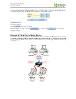
Page 33: ...to add to the ID list After all settings are configured click and then click to immediately apply the changes Example 2 Serial Port to Master Device Two serial ports connecting to different serial Mas...

Page 34: ...igured After the Parameter has been configured select the Serial Device Mode function menu for Port1 Port1 Serial Device Mode setup Port1 is the Modbus RTU Master device therefore Serial Device Mode i...

Page 35: ...ve device response time Enter the ID and then click to add to the list Click after configuring the slave device and ID to add to the list Port2 Serial Device Mode setup Port2 is the Modbus ASCII Maste...

Page 36: ...3 Modbus Gateway to Modbus Gateway Direct Link When the Modbus Slave and Modbus Master both uses the serial ports and is able to communicate with each other through the Ethernet connection then the M...

Page 37: ...User manual Version 1 0 Modbus Gateway and 2...

Reviews: