Chapter 3
SR7-8X
3-14
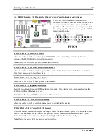
(12). D11: 5V Standby LED
D11 will light up after the power switch is pressed,
this LED will show you the 5V standby power
situation.
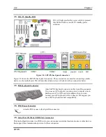
Figure 2-8. SR7-8X back panel connectors
Figure 2-8 shows the SR7-8X back panel connectors. These connectors are used for connecting outside
devices to the motherboard. We will describe which devices will attach to these connectors below.
(13). PS/2 Keyboard Connector
Attach a PS/2 keyboard connector to this 6-pin Din-connector.
If you use an AT keyboard, you can go to a computer store to
purchase an AT to ATX converter adapter, then you can
connect your AT keyboard to this connector. We suggest you
use a PS/2 keyboard for best compatibility.
(14). PS/2 Mouse Connector
Attach a PS/2 mouse to this 6-pin Din-connector.
(15). Serial Port COM1 & COM2 Port Connectors
This motherboard provides two COM ports, you can connect an external modem, mouse or other devices
that support this communication protocol to these connectors.
Summary of Contents for SR7-8X
Page 2: ......
Page 82: ...Chapter 4 SR7 8X 4 34 ...
Page 92: ...Appendix C SR7 8X C 4 ...
Page 102: ...Appendix F SR7 8X F 6 ...
Page 114: ...Appendix I SR7 8X I 4 ...


