
Chapter 3
SG-71
3-10
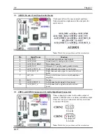
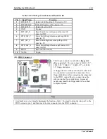
Pin Signal
Name
Function
1
VCC0
Front Panel USB Power
2
VCC1
Front Panel USB Power
3
DATA 0-
USB Port 0 Negative Signal
4
Data 1-
USB Port 1 Negative Signal
5
Data 0+
USB Port 0 Positive Signal
6
Data 1+
USB Port 1 Positive Signal
7
GND Ground
8
GND Ground
9
No Pin
No pin
10
GND Ground
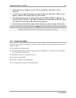
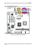
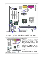
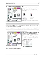
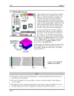
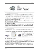
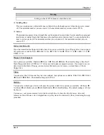
(7). IR1 Header: IR Header (Infrared)
There is a specific orientation for pins 1 through 6,
attach the connector from the IR KIT or IR device to
the IR header (FPIO3). This motherboard supports
standard IR transfer rates.
Note:
Watch the pin position and the orientation
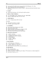
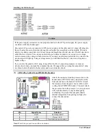
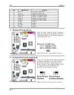
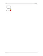
(8). JP3
Header:
BIOS
Protection Jumper Header
If you want to update the BIOS, please set this BIOS
protection jumper head to write protect disabled
position (pin 1 and pin 2 shorted), then you can
update your BIOS. After updating the BIOS, return
it to the default setting (Enabling the write
protection, set pin 2 and pin 3 shorted).
Note:
Watch the pin position and the orientation
Summary of Contents for SG-71
Page 2: ......
Page 50: ...Chapter 3 SG 71 3 18 ...
Page 84: ...Appendix A SG 71 A 4 ...
Page 88: ...Appendix B SG 71 B 4 ...
Page 92: ...Appendix C SG 71 C 4 ...
Page 110: ...Appendix H SG 71 H 6 ...
Page 114: ...Appendix I SG 71 I 4 ...


