Hardware Setup
2-1
Chapter 2. Hardware Setup
Before the Installation:
Turn off the power supply switch (fully turn off the +5V standby power), or
disconnect the power cord before installing or unplugging any connectors or add-on cards. Failing to do
so may cause the motherboard components or add-on cards to malfunction or damaged.
2-1. Install The Motherboard
Most computer chassis have a base with many mounting holes to allow motherboard to be securely
attached on and at the same time, prevented from short circuits. There are two ways to attach the
motherboard to the chassis base:
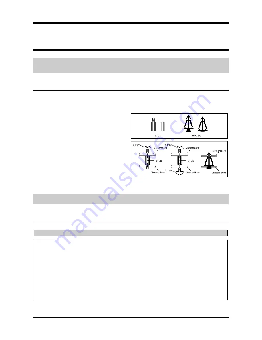
1. use with studs
2. or use with spacers
In principle, the best way to attach the board is to
use with studs. Only if you are unable to do this
should you attach the board with spacers. Line up
the holes on the board with the mounting holes on
the chassis. If the holes line up and there are
screw holes, you can attach the board with studs.
If the holes line up and there are only slots, you
can only attach with spacers. Take the tip of the
spacers and insert them into the slots. After doing
this to all the slots, you can slide the board into
position aligned with slots. After the board has been positioned, check to make sure everything is OK
before putting the chassis back on.
ATTENTION:
To prevent shorting the PCB circuit, please REMOVE the metal studs or spacers if they
are already fastened on the chassis base and are without mounting-holes on the motherboard to align with.
2-2. Install CPU and Heatsink
Note
•
Installing a heatsink and cooling fan is necessary for heat to dissipate from your processor.
Failing to install these items may result in overheating and processor damage.
•
The AMD Socket A processor will produce a lot of heat while operating, so you need to use a
large heat sink that is especially designed for the AMD socket A processor. Otherwise, it may
result in overheating and processor damage.
•
If your processor fan and its power cable are not installed properly, never plug the ATX power
cable into the motherboard. This can prevent possible processor damage.
•
Please refer to your processor installation manual or other documentation with your processor for
detailed installation instructions.
User’s Manual
Summary of Contents for KD7A
Page 1: ...KD7A Socket 462 System Board User s Manual 4200 0385 02 Rev 1 00 ...
Page 5: ...1 User s Manual ...
Page 18: ...14 14 KD7A KD7A ...
Page 20: ...1 2 Chapter 1 1 2 Layout Diagram KD7A ...
Page 64: ...B 2 Appendix B B 2 Appendix B KD7A KD7A ...
Page 66: ...C 2 Appendix C C 2 Appendix C KD7A KD7A ...
Page 68: ...D 2 Appendix D Click Yes 6 Click OK 7 Click Print to File 8 Click OK 9 KD7A ...


