EN - 24
BAL.0415.0 • 2018-10-22
7 Operation
TIG cold-wire feeder
7 Operation
7.1 Control elements
TIG cold-wire feeder
7.2 Connections and control elements
NOTICE
• The system may only be operated by qualified personnel (in Germany see TRBS 1203).
• Please also consult the operating instructions for the welding components, such as welding torch and power source
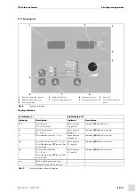
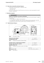
1
Main switch
2
Left display
3
Right display
4
Knob for setting parameters
5
Control lead (power source)
6
Coolant return (red)
7
Coolant supply (blue)
8
Complete central port
9
Mains plug
10
Welding current (power source)
11
Coolant return (red)
12
Coolant supply (blue)
13
Gas inlet
14
Control lead (power source)
Fig. 20
Overview of connections and control elements
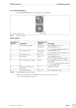
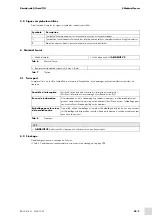
Symbol
Description
Main switch
Switching state I (LEDs green)
Switching state 0 (no power to the ABIDRIVE)
Left display
Right display
Knob for setting parameters
Coolant return
1
2
3
4
5
7
8
13
12
11
10
9
6
14


