54
10
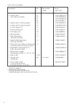
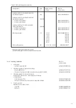
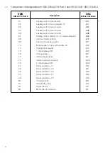
Comparison of designations to VDE-DIN 40719 Part 2 and IEC 61346-1/IEC 61346-2
VDE
IEC
DIN 40719 Part 2
Description
61346-1/61346-2
-S1
Auxiliary switch on mechanism
-BS1
-S2
Auxiliary switch on block magnet -Y1
-BL1
-S3
Auxiliary switch on switch shaft
-BB1
-S4
Auxiliary switch on switch shaft
-BB2
-S5
Auxiliary switch on switch shaft
-BB3
-S7
Fleeting contact
≥
30 ms for c.b. tripped indication
-BB4
-S8
Limit switch test position
-BT2
-S9
Limit switch service position
-BT1
-Y0
Block magnet on track with rectifier -V0
-RL2
-Y1
Closing block magnet
-RL1
-Y2
1. Shunt release OFF
-MO1
-Y3
Closing release
-MC
-Y4
Undervoltage release
-MU
-Y7
Indirect overcurrent release
-MO3
-Y9
2. Shunt release OFF
-MO2
-V1
Series rectifier for -Y1
-TR4
-V2
Series rectifier for -Y2
-TR1
-V3
Series rectifier for -Y3
-TR3
-V4
Series rectifier for -Y4
-TR6
-V9
Series rectifier for -Y9
-TR2
-M0
Charging motor
-MS
-K0
Antipumping relay
-KN
-R0
Series resistor
-RR
-M1
Motor drive for draw out
-MT

