7
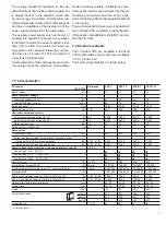
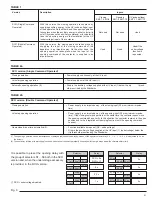
Contactor
Reference
VSC
7
VSC
12
VSC/P
7
VSC/P
12
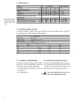
IEC 60470
Rated voltage
[kV]
4.1
7.2
12
7.2
12
Rated insulation voltage
Withstand voltage at 50 Hz
[kV]
23
28
23
28
Impulse withstand voltage
[kVbil]
60
75
60
75
Rated frequency
[Hz]
50-60
50-60
50-60
50-60
Rated service current
[A]
4.101
400
400
400
400
Short-time withstand current
Short-time withstand current for 1 s
[A]
4.5
6.000
4.000
6.000
4.000
Short-time withstand current for 30 s
[A]
4.5
2.500
2.500
2.500
2.500
Rated peak current
[kA]
4.6
15
15
15
15
Rated short-circuit time (tk)
[s]
4.7
1
1
1
1
Rated values
Operations / hour
[N.]
900
900
900
900
Rated load and overload characteristics in category of use:
- (Category AC4) 100 closing operations
[kA]
4.103, 4.104
4.000
4.000
4.000
4.000
- (Category AC4) 25 opening operations
[kA]
4.103, 4.104
4.000
4.000
4.000
4.000
Rated voltage of the switching devices and auxiliary circuits
4.8, 4.9
Feeder type 1 (24 ... 60 DC)
Feeder type 2 (110 ... 130 AC-DC)
Feeder type 3 (220 ... 250 AC-DC)
Normal current
[A]
4.4.101
400
400
400
400
Electrical life (category AC3)
[N.]
29.mar
100.000
100.000
100.000
100.000
Electrical life at rated current (cat. AC1 - electrical latching)
[N.]
29.mar
1.000.000
1.000.000
1.000.000
1.000.000
Mechanical life
[N.]
1.000.000
1.000.000
1.000.000
1.000.000
Short-circuit breaking capacity (O-3min-CO-3min-CO)
[A]
4.107, 6.104
6.000
4.000
6.000
4.000
Short-circuit making capacity (O-3min-CO-3min-CO)
[A]
4.107, 6.104
15.000
8.000
15.000
8.000
Opening time with electrical latching
[ms]
20..30
20..30
20...30
20...30
Closing time
[ms]
30..50
30..50
30...50
30...50
Weight
[Kg]
20
20
49(*)
49(*)
Overall dimensions
[mm] H
371
391
635
635
[mm]
W
350
350
531
531
[mm]
D
215
215
657
657
Tropicalisation
721-2-1
1.3. Characteristics
(*) Without fuses.
The energy needed for operation is not sup-
plied directly by the auxiliary power supply, but
is always “stored” in the capacitor which acts
as an energy accumulator, and therefore op-
eration always takes place with constant speeds
and times, regardless of the divergence of the
power supply voltage from the rated value.
The auxiliary power supply only has the aim of
keeping the capacitor charged. Consumption
is therefore minimal. The power required is less
than 5 W. In order to re-instate the rated en-
ergy value in the capacitor following an opera-
tion, there is an inrush of 15 W for a duration of
a few tens of milliseconds.
Careful selection of the components and a pre-
cise design make the electronic multi-voltage
feeder extremely reliable, unaffected by elec-
tromagnetic interference generated by the sur-
rounding environment and free of any emis-
sions which may affect other apparatus placed
in the vicinity.
These characteristics have made it possible for
the V-Contact VSC contactors to pass the elec-
tromagnetic compatibility tests (EMC) and ob-
tain the CE mark.
1.2. Versions available
The V-Contact VSC are available in the fixed
and withdrawable version with rated voltages
of 7.2 kV and 12 kV.
Their main characteristics are listed below.
Summary of Contents for V-Contact VSC Series
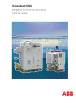
Page 1: ...V Contact VSC Installation and service instructions 7 2 12 kV 400 A ...
Page 2: ...1 ...
Page 35: ...33 50 50 49 49 Fig 18c Fig 18b ...
Page 39: ...1 ...

