27
1
2
3
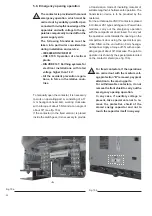
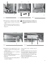
(2) Passing from the “isolated for test” to the
“isolated” position (disconnection of the aux-
iliaries)
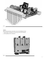
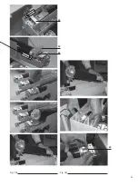
– release the mobile connector (1) (fig. 13) and
remove it from the fixed socket of the enclo-
sure (2) (fig. 12);
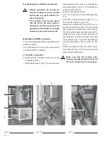
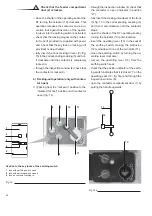
(3) Passing from the “isolated” to the “racked-
out” position
– bring the truck close to the switchgear;
– insert the hooking bracket (4) (fig. 11b - c)
and lock the wheels (3) (fig. 11a);
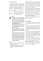
6.3. Accessories and tools for the operations
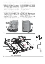
Caption
1 Operating lever of the earthing switches
2 Contactor racking-in/out lever
3 Tool for manual emergency opening operation
Fig. 15
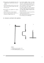
– move the two handles (5) (fig. 11d) at the
same time towards the median axis of the
contactor, and simultaneously pull the con-
tactor progressively towards the outside on
the truck by means of the handles;
– let go of the handles and continue extraction
until the contactor locks with the handles (fig.
11a) which click sideways locking the con-
tactor on the truck.
– unlock the wheels (3) (fig. 15a) and lift the
hooking bracket (4) (fig. 15f);
– lift the hooking bracket (4) (fig. 15f) and move
the truck away from the switchgear.
Summary of Contents for V-Contact VSC Series
Page 1: ...V Contact VSC Installation and service instructions 7 2 12 kV 400 A ...
Page 2: ...1 ...
Page 35: ...33 50 50 49 49 Fig 18c Fig 18b ...
Page 39: ...1 ...

