25
5
5
5
5
4
2
1
3
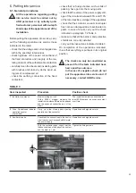
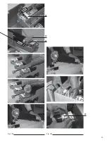
Fig. 11d
Fig. 11e
Fig. 11f
(2) Passing from the “isolated” to the “isolated
for test” position (connection of the auxilia-
ries)”.
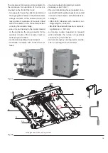
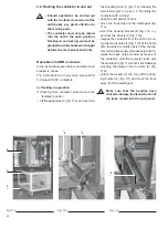
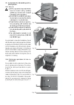
– Insert and hook up the mobile connector (1)
(fig. 13) in the fixed socket of the enclosure
(2) (fig. 12).
Fig. 12
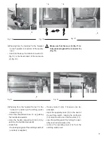
(3) Passing from the “isolated for test” to the
“racked-in” position (with earthing switch
closed) (fig. 14).
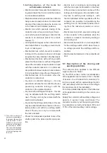
– close the compartment door (1) by pushing
the handle downwards;
– close the feeder compartment door (2) by
pushing the handle downwards;
– check that:
• the locking magnet of the earthing switch (if
provided) is supplied;
Fig. 13
• the key locks (7-8-9), if foreseen, are de-
activated;
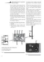
– insert the operating lever (13) in the seat of
the earthing switch, making the protrusion
(12) coincide with one of the two slots (11);
– open the earthing switch by turning the oper-
ating lever anti-clockwise (13);
– remove the operating lever (13) from the
earthing switch seat;
Make sure that the lever (3) (fig. 11) is
fully pressed against the connector (1)
(fig. 11).
!
Summary of Contents for V-Contact VSC Series
Page 1: ...V Contact VSC Installation and service instructions 7 2 12 kV 400 A ...
Page 2: ...1 ...
Page 35: ...33 50 50 49 49 Fig 18c Fig 18b ...
Page 39: ...1 ...

