16
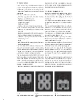
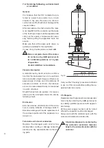
– Interpose a spring and a flat washer between
the head of the bolt and the connection.
– The use of bolts according to DIN class 8.8
Standards is recommended, also referring to
what is indicated in the table.
– In the case of cable connections, strictly fol-
low the manufacturer’s instructions for mak-
ing the terminals.
Bolt
Recommended tightening torque (1)
Without lubricant
M6
10.5 Nm
M8
26 Nm
M10
50 Nm
M12
86 Nm
(1) The nominal tightening torque is based on a friction
coefficient of the thread of 0.14 (distributed value the
thread is subjected to which, in some cases, is not neg-
ligible).
Take into account the deviations from the general Stan-
dards table (for example, for contact systems or termi-
nals) as foreseen in the specific technical documenta-
tion.
The thread and surfaces in contact with the heads of
bolts must be slightly oiled or greased, so as to obtain
a correct nominal tightening torque.
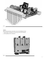
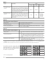
Connection to be made by the customer (*)
Pins KM1-1 and KM1-2 must always be supplied, both in the SCO and DCO version (also see
par. 5.8.). The polarity is not important since the internal circuits take both AC or DC signals. For
further details, consult the electric circuit diagram enclosed with the apparatus.
N. of pin
Connections
Meaning of each pin
KM1-1
Auxiliary power supply
Auxiliary power supply AC or DC (pole 1)
KM1-2
Auxiliary power supply
Auxiliary power supply AC or DC (pole 2)
KM1-3
Binary output n° 1
Indication of Unit ready (pole 1)
KM1-4
Binary output n° 1
Indication of Unit ready (pole 2)
KM1-5
Binary input n° 1
Protection trip (pole 2)
KM1-6
Binary input n° 1
Protection trip (pole 1)
KM1-7
Binary input n° 2
Closing (pole 1)
KM1-8
Binary input n° 2
Closing (pole 2)
KM1-9
Binary input n° 3
Opening (pole 1)
KM1-10
Binary input n° 3
Opening (pole 2)
KM1-11
Binary input n° 3
Undervoltage (pole 1)
KM1-12
Binary input n° 3
Undervoltage (pole 2)
Earthing
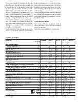
For the fixed version contactor, carry out
earthing by means of the special hole marked
with the relative symbol. Clean and degrease
the area around the screw to a diameter of
about 30 mm and, on completion of assembly,
cover the joint again with Vaseline grease.
Use a conductor (busbar or cord) with a cross-
section conforming to the Standards in force.
Connection of the auxiliary circuits
The cables to be used for connection of the
auxiliary circuits must have a rated voltage Uo/
U of 450/750 V and be insulated for 3 kV test.
Note: before carrying out the test, disconnect the earthing
connection of the electronic feeder.
Also remember that the auxiliary circuits must be checked
at the maximum voltage of 2 kV in accordance with what is
prescribed in the Standards.
The cross-section of the connection cables
must not be less than 1.5 mm
2
.
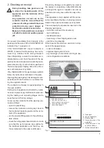
Connection of the contactor auxiliary circuits
must be made by means of the socket with ter-
minal box mounted on the front of the electronic
card.
Outside, the wires must run through metallic
pipes or ducts suitably earthed.
(*) Only for fixed contactors.
The withdrawable con-
tactors are cabled in the
factory.
Summary of Contents for V-Contact VSC Series
Page 1: ...V Contact VSC Installation and service instructions 7 2 12 kV 400 A ...
Page 2: ...1 ...
Page 35: ...33 50 50 49 49 Fig 18c Fig 18b ...
Page 39: ...1 ...

