


9.4 Repairs
Repair of surface damage:
•
Carry out repair work immediately after a
defect has been discovered
•
Completely remove all rust from damaged
paintwork areas on steel sheet and other
steel parts by mechanical means, e.g. with a
wire brush
•
Lightly grind the surrounding paint coat and
carefully degrease the entire area. Then
immediately apply an anti-rust primer and,
after an appropriate hardening time, apply
the top coat. Only use suitable and
compatible paint products
•
Apply the top coat in standard RAL 7035 colour,
or the relevant special colour
•
Carefully remove any white rust on
aluminium/zinc surfaces with a wire brush or
cleaning pad, e.g. Scotch-Brite, and clean
loosely adhering particles with a dry,
non-fraying cloth. Next treat the cleaned
parts with zinc spray or zinc powder paint
and, finally, treat with aluminium spray for
colour matching
•
Carefully remove any white rust from
passivated operating parts and rust
formation on phosphatised parts with a wire
brush or metal-free cleaning pad, e.g.
Scotch-Brite, and clean with a dry cloth. Then
grease evenly (with Isoflex Topas NB 52)
9.4.1 Switchgear in general
•
Follow the maintenance instructions in the
manuals for individual equipment components
•
Check that the bolt connections at the
contact points in the busbar system and the
earth connections are tight, and that the
contact system functions correctly
•
Where necessary, grease slide plates and
bearings in the panel again or thoroughly
clean them. Then grease them again with
Isoflex NB 52 lubricant
•
Top up grease on contact areas in the contact
system when corroded or otherwise as
necessary, or, when lubrication is inadequate
or missing, thoroughly clean the areas concerned
and grease them again with Isoflex Topas NB
52 lubricant
9.4.2 Replacement of complex functional groups
Precise matching of functions for control,
interlocking and signalling only permits
replacement of individual components to a
limited extent.
The contactor truck, earth switch and interlocking
assemblies are prefabricated and tested at the
works, maintaining high quality standards. In the
case of faults, they must therefore be serviced
or completely replaced by ABB certified technicians.
9.4.3 Replacement of parts
9.4.3.1 Trip coil replacement for V7/ZVC
Undo the three screws (step 1) attaching the
microswitches’ mounting plate to the truck
traverse (on the left-hand side of the truck
looking from the front). Slide trip coil out of the
trip operating mechanism (step 2), disconnect
its wires and remove the two screws holding it
to the mounting plate (step 3). Fit the new trip
coil reversing the steps taken in the removal
process.
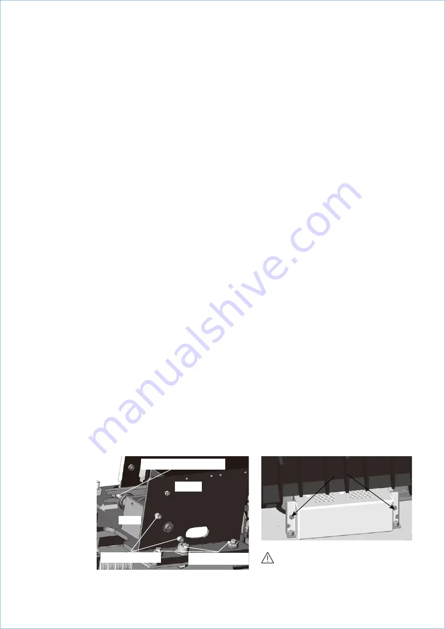
9.4.3.2 Feeder unit replacement V7/ZVC
Undo the two screws holding the feeder unit to
the truck (on the right-hand side of the truck
looking from the front). Remove feeder unit
from the truck and disconnect its wires.
Fit the new feeder unit reversing the steps
taken in the removal process.
Feeder unit
Remove these 2 screws
Caution!
Ensure the replacement feeder unit is of
the same voltage and configuration.
Step 1.
Remove these three screws
Trip Coil
Mounting
Plate
Step 2.
Slide trip coil out of operating mech.
Step 2.
Remove these two screws
48
U N I G E A R Z V C
M E D I U M V O L T A G E P R O D U C T S
—
9/2 Trip Coil
—
9/3 Feeder Unit
—
9/2