


64
ABB Power Distribution
Figure 7/3: Slide the contact system over from the arbor onto the
contact arm and allow it to engage there
4.2
Contact arm
4.3
Contact system
4.4
Internal tension springs
(4.5)
Socket head bolt
4.6
Insulating sleeve
127
Arbor
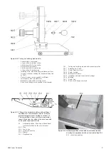
Figure 7/4: Motor-driven withdrawable part in an intermediate
position close to the test/disconnected position, with
fitted crank for manual operation and breaker front plate
removed
10.3
Control wiring plug connector for withdrawable
assembly
13.2.1 ON push rod
13.24
Roller
13.26
Lever
13.92
Angle lever
121
Hand crank
127
4.3
127.2
4.3
4.6
4.3
(4.5)
4.2
127
4.4
13.26
13.2.1
13.24
13.92
10.3
Figure 7/1: Fit the contact system back-to-front on the thin end of
the arbor and slide it onto the thicker shank area
4.3
Contact system
127
Arbor
127.1
Journal
Figure 7/2: Preparation for assembly of the VD4 E contact system.
Handling as described in figure 7/1
4.3
Contact system
127.2
Arbor for VD4 E
121
127.1
Summary of Contents for UniGear ZS1
Page 66: ...ABB Power Distribution 67 ...