


ABB Power Distribution
23
5
Erection of the switchgear on site
In the interests of the best possible erection
sequence, and in order not to endanger the high
quality standard of the ZS1 switchgear, local
erection should only be carried out, or at least
responsibly managed and supervised, by specially
trained skilled personnel.
5.1
Site requirements
On commencement of installation at site, the
switchroom must be completely finished, provided
with lighting and site electricity supply, lockable, dry
and with facilities for ventilation. All the necessary
preparations such as wall openings, ducts, etc. for
laying of the power and control cables up to the
switchgear must already be complete. Where
panels have top-mounted structures for earthing
switches or instrument transformers, it must be
ensured that the ceiling height is sufficient for the
opening travel of the pressure relief flaps.
The ceiling height is also to be checked when there
is a top-mounted pressure relief duct.
Compliance with the conditions for indoor
switchgear to VDE 0670 part 1000/IEC 60694,
including the conditions for the „minus 5 indoor“
temperature class must be ensured.
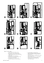
5.2
Foundations
(Figures 5/1 to 5/5)
The switchgear is preferably to be erected on a
foundation frame set into the switchroom floor or
on a raised false floor.
The guideline structural data listed below facilitate a
rough calculation of the space required and
preliminary planning of the room design for a
switchgear project. When the final construction
documents are compiled, the binding data
supplied by ABB Calor Emag must always be taken
into account!
The stipulations of DIN 43 661 are also to be
complied with when the foundation is laid. This
particularly applies to the evenness and
straightness tolerances of the switchgear.
Note:
The construction data for the ceiling openings for
incoming conductors do not aply to trunking bars
without earthed coatings. Broader ceiling openings
are required in such cases.
Dimension chart of structural data
(See also figures 5/1 to 5/4)
Panel dimensions
[mm]
Width
650
800 1000
Depth
1300
1300
1300
1350
Minimum dimensions
[mm]
Door height
1)
2400
2400
2400
2400
in the switching room
Door width
850
1000
1200
1200
Aisle width
2)
1350
1500
1700
1700
Assembly opening
in ceiling:
• Width
1000
1000
1200
1200
• Length
1500
1500
1500
1500
1)
Upright transport of panels with a height of 2200 mm.
2)
Pay attention to VDE 0101
Summary of Contents for UniGear ZS1
Page 66: ...ABB Power Distribution 67 ...