


- 66 -
UMC100-FBP
Universal Motor Controller
UMC100-FBP
Technical Description
FieldBusPlug / Issue: 03.2012
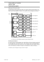
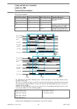
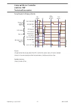
Checkback Monitoring
The UMC can be parameterised to monitor that the motor was really started using a checkback signal. By
default the actual motor current is monitored. But it is also possible to use an auxiliary contact mounted
on the main contactor.
If checkback monitoring via motor current is active it is checked that the measured current rose above
20 % within the Checkback Delay Time (t
cbd
) after switching on the main contactor. Otherwise when the
motor is switched off the function checks that the motor current is zero at the latest after the Checkback
Delay Time.
For checkback via contactors one or more auxiliary contacts must be installed and wired to the UMC's
digital input DI0. The number of monitored signals depends on the selected control functions which are
described in the following sections.
=================================\--------/=====================
----/=======\-----------------------------------------/=========
------/==============================\------------------------/=
------------------------------------------------------------/===
t
cbd
t
cbd
t
cbd
Related Parameters
•
Checkback Time
•
Checkback Mode
Using the Digital UMC Inputs
The UMC inputs DI0 ... DI5 are digital inputs according to IEC61131. They can be used to connect status
and control signals to the UMC. UMC's reaction to these signals can be adapted in a wide range to cover
typical user needs (e.g. starting the motor). The status of each digital input is available in the monitoring
telegram sent to the PLC/DCS.
Using the Inputs DI3-DI5
The inputs DI3 to DI5 can be used for local motor control. DI5 is always the stop input whereas DI4 starts
the motor in a forward direction and DI3 in a reverse direction (if supported by the active control function).
If inching mode is enabled the stop can still be used.
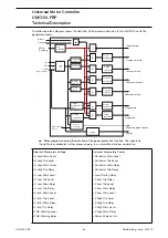
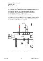
Using the Multifunction Inputs DI0-DI2
The digital inputs DI0, DI1 and DI2 are called multifunction inputs because their function can be adapted
flexibly depending to your application requirements. The following diagram shows the way the multifunc-
tion inputs work.
The three multifunction inputs operate fully independent - i.e. for each input an own delay time and func-
tion can be selected. Functions like 'test position', 'stop motor' etc. internally pass an OR gate so the
UMC does not differentiate from which digital input the signal came.
If an input is configured as fault input the behaviour is different. For each input its own internal error signal
is available and a fault text can be specified which is displayed on the LCD panel in the event of this error.
You can thus find out what input actually triggered the fault. Faults can be auto acknowledged when the
fault has been rectified.
Start
Stop
Check-
back
Check-
back
Fault
Summary of Contents for UMC100-FBP
Page 1: ...Technical Description Universal Motor Controller UMC100 FBP ...
Page 157: ......


