


- 101 -
UMC100-FBP
Universal Motor Controller
UMC100-FBP
Technical Description
FieldBusPlug / Issue: 03.2012
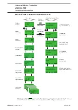
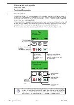
Motor Protection Parameters
Within this submenu all motor protection r
elated parameters can be configured. The diagram below
shows the organisation of the different parameter masks in the menu tree.
Setting Ie 1
Setting Ie 2*
Trip class
Current factor
PTC
Cooling mode
Cooling time
Restart level %
Locked rotor (LR)
Thermal load warnlev
Phases
Over/under current
Int. earthfault
Voltage DIP**
Over/under voltage**
Voltage imbalance**
Load startup delay**
Over/under power**
Power factor**
Power quality**
2 Protection
2.1
2.2
2.3
2.4
2.5
2.6
2.7
2.8
2.9
2.10
2.11
2.12
2.13
2.14
2.15
2.16
2.17
2.18
2.19
2.20
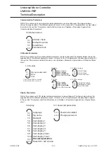
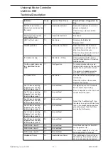
LR trip level
LR trip delay
2.9 Locked Rotor
2.9.1
2.9.2
Phase loss protect.
Phase imb. trip lev.
Phase imb. warn lev.
Phase reversal
Check phase sequence
2.11 Phases
2.11.1
2.11.2
2.11.3
2.11.4
2.11.5
Low curr trip level
Low curr trip delay
Low curr warn level
Low curr warn delay
High curr trip level
High curr trip delay
High curr warn level
High curr warn delay
2.12 Over / under current
2.12.1
2.12.2
2.12.3
2.12.4
2.12.5
2.12.6
2.12.7
2.12.8
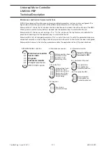
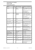
Enable voltage DIP
Voltage DIP duration
Autorestart enable
Autorestart window
Autorestart delay
DIP restart level
DIP level
2.14 Voltage DIP
2.14.1
2.14.2
2.14.3
2.14.4
2.14.5
2.14.6
2.14.7
Earth flt. trip lev.
Earth flt. trip delay
Earth flt. warn lev.
Earth flt. warn delay
Earth fault detection
2.13 Int. earthfault
2.13.1
2.13.2
2.13.3
2.13.4
2.13.5
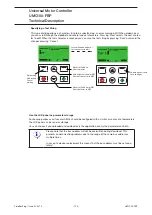
U low trip level
U low trip delay
U low warn level
U low warn delay
U high trip level
U high trip delay
U high warn level
U high warn delay
2.15 Over / under voltage
2.15.1
2.15.2
2.15.3
2.15.4
2.15.5
2.15.6
2.15.7
2.15.8
U imb trip level
U imb trip delay
U imb warn level
U imb warn delay
2.16 Voltage imbalance
2.16.1
2.16.2
2.16.3
2.16.4
P low trip level
P low trip delay
P low warn level
P low warn delay
P high trip level
P high trip delay
P high warn level
P high warn delay
2.18 Over / under power
2.18.1
2.18.2
2.18.3
2.18.4
2.18.5
2.18.6
2.18.7
2.18.8
PwrFactor trip level
PwrFactor trip delay
PwrFactor warn level
PwrFactor warn delay
2.19 Power factor
2.19.1
2.19.2
2.19.3
2.19.4
THD warn level
THD warn delay
2.20 Power quality
2.20.1
2.20.2
*) Polechanging starter only
**) With voltage module only
The parameters are described in detail in the section "Parameters and Data Structures
on a Fieldbus->Parameter Organisation-> Motor Protection Parameters".
Summary of Contents for UMC100-FBP
Page 1: ...Technical Description Universal Motor Controller UMC100 FBP ...
Page 157: ......


