3
a) Power
transfer
Power is transfered from the motor through a gear
wheel and threaded shaft to the operating axel. The
direction of operation for open and close control can
be reversed by changing the motor’s direction of
rotation. The threaded shaft gear is assembled from
a round stainless steel shaft and one or two bronze
nuts. The shaft is self-locking which means that the
operating device cannot be rotated with a force from
the operating axel. This also applies if the operating
device is in the central position. The nuts transfer
the power through the specially formed lever to the
operating axel. The lever is formed so that it can be
locked in the extream position.
By disengaging the coupling ring, manual operation can
be performed by means of the control lever.
Both the gear wheel and the threaded shaft are
greased with low temperature grease which ensures
correct operation in temperatures as low as –50°C.
b) Mechanical
locking
The unit is fi tted with a locking device which also
includes a switch to prevent the motor from operat-
ing. The locking unit mechanically locks the operating
device and is strong enough to withstand the driving
force of the motor if the blocking switch S12 fails. The
locking unit locks both the motor operating device and
the manual operating device.
c) Electrical
operation
Motor operating device type UEMC 40 A1_, B1_,
and D1_ are fi tted with a lower level of electrical
components, and require a separate control unit, such
as UEZJ 1 or UEZJ 2.
Refer to circuit diagram: 31 UEMC 79.
Motor operating device type UEMC 40 A2_, B2_, and
D2-_are equipped with a complete control system
including contactors, I- and O-push buttons and m.c.b.
Refer to circuit diagram: 31 UEMC 81.
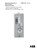
1. General
The UEMC 40 A_, UEMC 40 B_ and UEMC 40 D_ motor
operating devices are intended for indoor mounting on
medium voltage disconnectors and earthing switches.
The operating device is reliable in changing temperature
and humidity conditions.
Operation can be performed both electrically or by
means of the manual operating lever. Operating time
is about 5...8 s depending on the type of device and
loading conditions.
2. Standards
The motor operating device complies with
– IEC 265 (1983)
– VDE 0530 motor voltage test
3.
Transport and storage
The motor operating device can be transported in any
position, and should be stored indoors in a dry area.
4. Construction
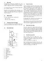
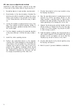
Fig. A
1. Power
unit
2. Limit
switch
3. Guide
pin
4. Coupling
ring
5. Locking
catch
6. Motor
7. Terminal
block
8. Control push button
9. M.c.b.
10. Contactor
11. Lever
12. Nut
Summary of Contents for UEMC 40 A Series
Page 26: ...26 26 ...
Page 50: ...50 50 ...
Page 74: ...74 74 ...
Page 86: ...86 86 ...
Page 87: ...87 ...

