Operation Manual / TPL65-A32 / -A33 / -A36 + TPL69-A32 / -A33
Disassembly and assembly
8
Dismantling and installing the turbine
diffuser and nozzle ring
8.6
Page 90
Sept
em
be
r 2
014
H
ZT
L24
98_
EN
R
ev
is
ion A
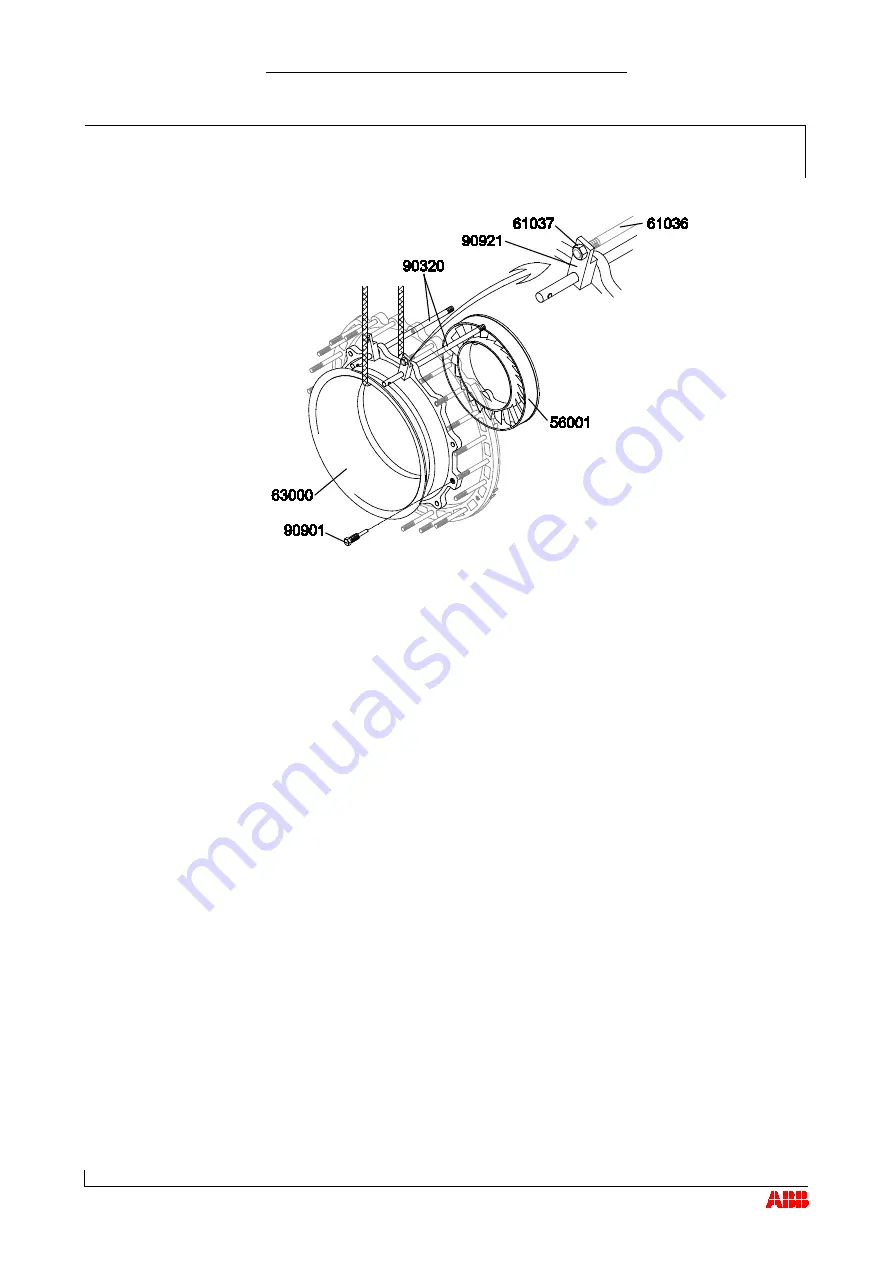
Replace two screws (61056) in the gas outlet casing with two guide
studs (90320) in the upper section of the turbine diffuser (63000).
Fit clamps (90921) over the guide studs (90320) and the studs
(61036).
To secure the work, screw the nuts (61037) onto the start of stud
threads (61036).
Remove the remaining screws (61056) and Verbus Ripp® washers
(61057).
Press the turbine diffuser (63000) free using the press-off screws
(90901) and pull it out it until the clamp (90921) is up against the nut
(61037).
Loop the lifting gear around the turbine diffuser (63000) and secure it
to a crane.
Remove nuts (61037) and clamps (90921).
Fully withdraw the turbine diffuser and remove it.
Remove the guide studs (90320).
Pull nozzle ring (56001) forward and remove.
Installing the turbine diffuser and nozzle ring
Install the nozzle ring and turbine diffuser in the reverse order of
removal.
Coat the screw threads with high-temperature grease.
Align nozzle ring with holes or cams in gas inlet casing.
© Copyright 2014 ABB. All rights reserved.


