Operation Manual / TPL65-A32 / -A33 / -A36 + TPL69-A32 / -A33
Taking out of operation at short notice
9
Locking the rotor
9.2
Page 101
Sept
em
be
r 2
014
H
ZT
L24
98_
EN
R
ev
is
ion A
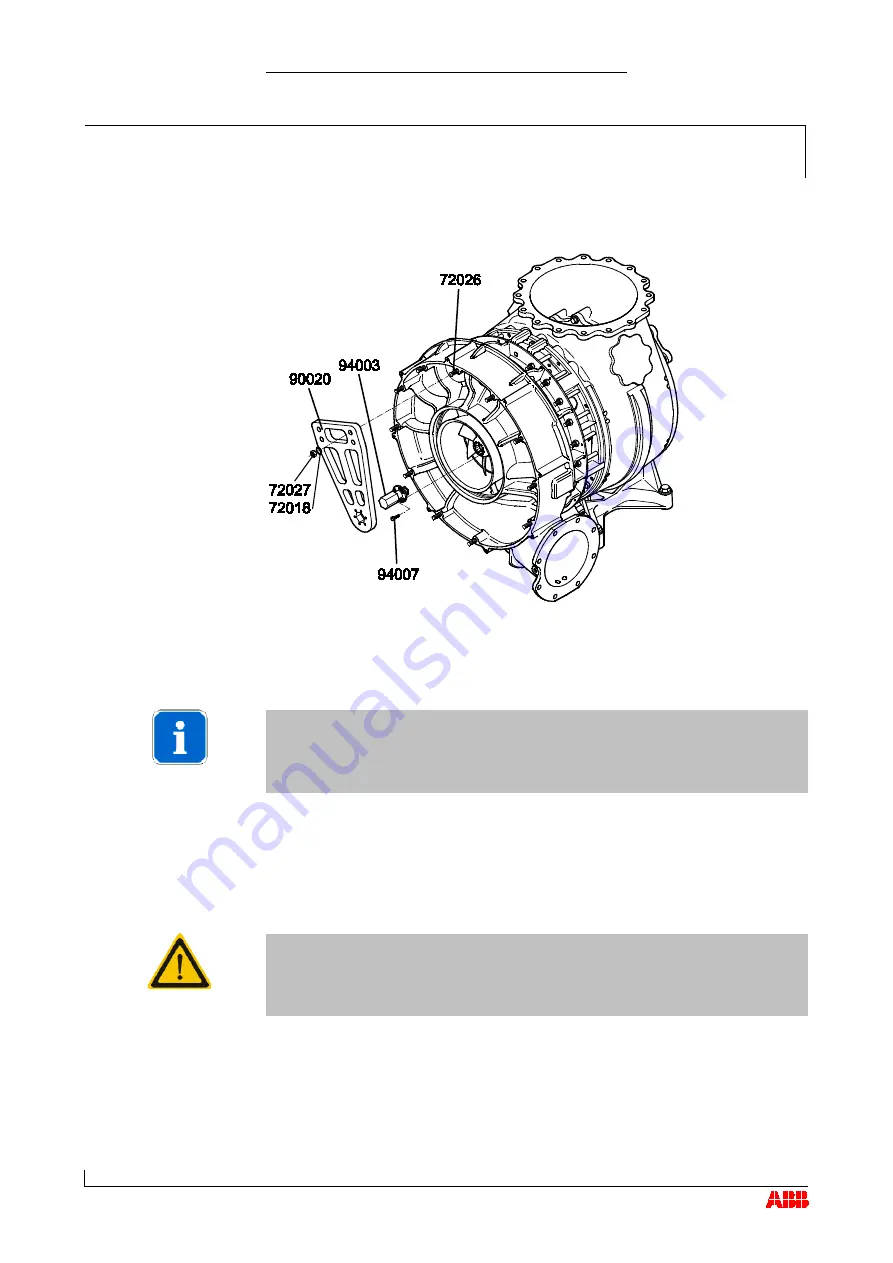
Locking rotor TPL65-A32 / A33 / A36
Remove silencer or air suction branch.
NOTICE
Carry out work as described in chapter Removing and fitting.
Insert locking flange (94003) into compressor wheel.
Position screws (94007) in unused threaded holes of compressor
wheel and tighten them as specified in following Table of tightening
torques .
CAUTION
Don't remove any balancing screws from compressor wheel. Use only
unoccupied threaded holes to fit lifting device.
Position assembly / disassembly device (90020) over studs (72026)
and locking flange (94003).
Turn compressor wheel so that locking flange hexagon aligns with
hexagon in assembly / disassembly device (90020).
Tighten nuts (74027) complete with washers (72018) on compressor
casing as specified in following Table of tightening torques.
© Copyright 2014 ABB. All rights reserved.


