ABB SYN 5201 Operating Instructions Manual Download Page 135

Operating Instructions


SYN 5201/SYN 5202


Document No Art Part 

Language  Revision 

page 

abb


ABB Switzerland Ltd 

3BHS109762 E01


en D 135 

Template: CHIND Techn doc stand, A4 P de, R1.DOT; Filename: 3BHS109762E01 D.doc; Print: 12/6/2011 5:48:00 PM; Save: 12/1/2011 2:37:00 PM; CHIND No. 3BHS109763 ZAB D14 Rev. -; I-Q 

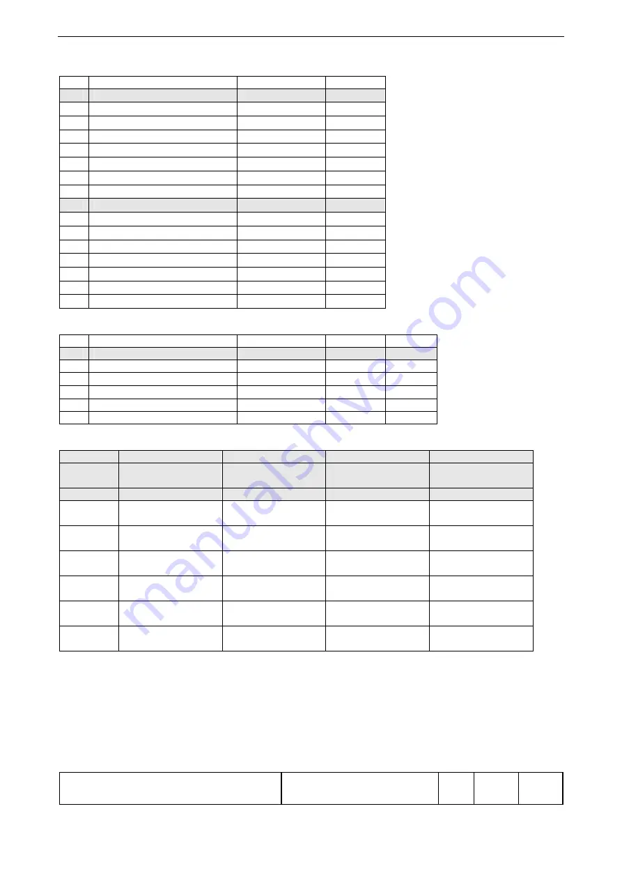
Parameter settings: Configuration parameters 

 Parameter 

Abbreviation Value 

Digital inputs 


1.1 

Digital input 1 

I 1 


1.2 

Digital input 2 

I 2 


1.3 

Digital input 3 

I 3 


1.4 

Digital input 4 

I 4 


1.5 

Digital input 5 

I 5 


1.6 

Digital input 6 

I 6 


1.7 

Digital input 7 

I 7 


Digital outputs 


2.1 

Digital output 1 

O 1 


2.2 

Digital output 2 

O 2 


2.3 

Digital output 3 

O 3 


2.4 

Digital output 4 

O 4 


2.5 

Digital output 5 

O 5 


2.6 

Digital output 6 

O 6 


2.7 

Digital output 7 

O 7 


Parameter settings: Channel 2 (SYN 5202) 

 Synchrocheck 

Abbreviation Value  Unit 

Synchrocheck parameters 


1.1 Slip 

limit 

smax 


1.2 Angle 

limit 

max 


DEG 

1.3 

Max. voltage difference 

Umax 


1.4 

Max. zero voltage 

U0max 


1.5 Nominal 

voltage 

Un 


VAC 

SYN 5500 

Device

 No


Device 1 

Device 2 

Device 3 

Device 4 

Name 


Jumper 

open / closed 

open / closed 

open / closed 

open / closed 

W1 


W2 


W3 


W4 


W5 


W6 


Summary of Contents for SYN 5201

Page 1: ...abb 3BHS109762 E01 Rev D Edition december 2011 SYNCHROTACT 5 Operating Instructions SYN 5201 SYN 5202 ...

Page 2: ...n doc stand A4 P de R1 DOT Filename 3BHS109762E01 D doc Print 12 6 2011 5 48 00 PM Save 12 1 2011 2 37 00 PM CHIND No 3BHS109763 ZAB D14 Rev I Q 2011 ABB Switzerland Ltd Turgi We reserve all rights in this document and in the information contained therein Reproduction use or disclosure to third parties without express authority is strictly forbidden ...

Page 3: ... 12 6 2011 5 48 00 PM Save 12 1 2011 2 37 00 PM CHIND No 3BHS109763 ZAB D14 Rev I Q Content 1 GENERAL INFORMATION 5 2 FUNCTIONAL PRINCIPLE 7 3 HARDWARE CONSTRUCTION 25 4 PARAMETERS ACTUAL VALUES EVENTS 31 5 ENGINEERING INSTRUCTIONS 67 6 INSTALLATION AND DISPOSAL 77 7 OPERATING INSTRUCTIONS 79 8 COMMISSIONING 91 9 MAINTENANCE AND FAULTS 101 10 TECHNICAL DATA 119 11 SCHEMATICS 125 12 RECORD AND QUES...

Page 4: ...ent No Art Part Language Revision page abb ABB Switzerland Ltd 3BHS109762 E01 en D 4 Template CHIND Techn doc stand A4 P de R1 DOT Filename 3BHS109762E01 D doc Print 12 6 2011 5 48 00 PM Save 12 1 2011 2 37 00 PM CHIND No 3BHS109763 ZAB D14 Rev I Q ...

Page 5: ...ous voltages This symbol indicates that when handling the equipment dangerous voltages occur which can cause death or serious injury The sections of text marked with Caution contain information on situations which can lead to material damage or equipment failure if the instructions are disregarded The sections of text marked with Note provide additional information This must be taken into consider...

Page 6: ...ent No Art Part Language Revision page abb ABB Switzerland Ltd 3BHS109762 E01 en D 6 Template CHIND Techn doc stand A4 P de R1 DOT Filename 3BHS109762E01 D doc Print 12 6 2011 5 48 00 PM Save 12 1 2011 2 37 00 PM CHIND No 3BHS109763 ZAB D14 Rev I Q ...

Page 7: ...n provides the highest security against incorrect paralleling SYN 5202 consists of two independent channels with different hardware and software This dual channel property maximizes security against incorrect paralleling All parameters required for paralleling are stored in a parameter set The paralleling conditions and the characteristics of the voltage and frequency matchers are defined in this ...

Page 8: ... four function blocks 1 Measuring 2 Voltage and frequency matching 3 Monitoring of paralleling conditions 4 Paralleling command generation In the following figure the block circuit diagram of the basic paralleling functions of SYNCHROTACT 5 is simplified and shows a single channel configuration The individual functions are described more precisely in the following sections U1 U2 0 0 U U f f U Umax...

Page 9: ...U U IU1I IU2I U 0 Adjustable voltage is lower U 0 Adjustable voltage is higher Slip s 100 1 2 1 f f f s s 0 Adjustable frequency is less e g generator is sub synchronous s 0 Adjustable frequency is greater e g generator is oversynchronous Phase angle difference 2 1 0 Adjustable frequency is lagging 0 Adjustable frequency is leading Acceleration ds dt s s dt ds x x x 2 56 1 Every 0 5 s an average v...

Page 10: ...istors differential amplifiers low pass filters and A D converters Voltage measurement channel 2 SYN 5202 only The two input voltages U1 and U2 are passed through high impedance input resistors and differential amplifiers The signal for the amplitude value is formed from this by conversion and filtering For zero passage detection the signal is filtered and passed through a comparator The signals p...

Page 11: ...ween Umin and Umax and the voltage U2 is greater than U0max the adjusting commands are released The direction of the adjusting commands depends on the polarity of U As an additional condition both frequencies must be in the range fn 5 Hz S05001 0 130 U U1 line or busbar U2 generator U0max 0 to 49 Umin 50 to 95 Un 100 50 to 130 VAC Umax 105 to 130 adjusting commands blocked adjusting commands relea...

Page 12: ...e command length does not fall below a settable minimum value After an adjusting command the system waits for the set pulse interval ts U so that the actual values can stabilise to the new setpoint Voltage matching with variable intervals The function INVERSE U changes the way the voltage matcher functions The pulses are now always the same length but the intervals are inversely proportional to th...

Page 13: ...nd 2 3 of smax there is a range where no adjustment takes place The adjusting pulse is discontinued as soon as the slip passes through zero The command length does not fall below a settable minimum value After an adjusting command the system waits for the set pulse interval ts f so that the actual values can stabilise to the new setpoint S00005 df dt tp f ts f smax s 0 1 2 smax smax s t Time Adjus...

Page 14: ... voltage carrying lines The monitoring of the paralleling conditions enables a paralleling command CHK RELEASE if the following conditions are fulfilled simultaneously the phase angle difference is within the tolerance band the slip is within the tolerance band the voltage difference is within the tolerance band the voltage does not fall below minimum voltage the maximum voltage is not exceeded th...

Page 15: ... a source can be asynchronous or synchronous at any time The paralleling command is issued in the mode in which all conditions are fulfilled first In SYN 5202 the actuation of the paralleling relays takes place separately in both channels Asynchronous sources It is called asynchronous sources if the two lines to be paralleled or generator and line are asynchronous before the circuit breaker is clo...

Page 16: ...mmands in a synchronization sequence or blocks command generation after the first paralleling command of each synchronization sequence 2 3 Test functions In order to match the SYNCHROTACT 5 to the installation three test functions are provided 1 TEST ton determines the paralleling time and tunes the measuring voltages with the circuit breaker closed 2 TEST U Match tunes the voltage matcher to the ...

Page 17: ...ed according to the following formula 5 Uo U dt dU 3 With this dU dt value the generator voltage is brought back to approx 96 4 Ten seconds later the generator voltage is brought to approx 100 with the same dU dt value After a further ten seconds dU dt is calculated again and shown on the display 2 3 3 TEST f Match This test function proceeds as follows 1 The slip is adjusted until this lies in th...

Page 18: ...t run of synchronization in which synchronization takes place normally by means of adjusting commands but the paralleling command is sent via a configurable relay rather than the command relay TEST t on parameter paralleling command is deliberately given TEST U Match parameter voltage adjusting commands are deliberately given TEST f Match parameter frequency adjusting commands are deliberately giv...

Page 19: ...necessary to select the parameter set via the digital inputs before starting the synchronization process The parameter set and the relay for selecting the paralleling points become active following the Start signal In Blocked Without Error status the selected parameter set is also active and the corresponding relay is pulled down for selection of the paralleling point This allows actual value cali...

Page 20: ...l command relays If the contacts fail to open again after a command has been given the contact monitoring prevents the synchronization from being selected again This signal can be made available externally through corresponding configuration of the digital outputs so that the connection of the command circuit can be blocked This function is also used to monitor the internal circuits for short circ...

Page 21: ...is used in the SYNCHROTACT 5 device for the date and timestamp of event logger and transient recorder There are three ways of synchronizing these with an external clock Relative synchronization by means of pulses pulse synchronization the time of the connected PC can be read into the device once using SynView The synchronization prevents the clock time from drifting apart by means of periodic puls...

Page 22: ...inction is made between service control and operating control Service control for commissioning and maintenance 1 Controls on the unit keypad LCD standard 2 Local control using PC SynView direct link SYNCHROTACT to PC 3 Remote control through PC over the network either via SynView interface Standard or over IEC 61850 interface Option Operating control for normal synchronizing operation 1 Conventio...

Page 23: ...operating interface is used to transmit the data which are relevant to normal operation Writing to digital inputs Start Stop Release DB selection of parameter set and paralleling point Reset Reading the digital outputs ERROR READY OPERATING U U f f back indication of paralleling point selection all configured output signals Reading the status displays U Umax s smax max U1 U2 0 COMMAND CHK RELEASE ...

Page 24: ...nt No Art Part Language Revision page abb ABB Switzerland Ltd 3BHS109762 E01 en D 24 Template CHIND Techn doc stand A4 P de R1 DOT Filename 3BHS109762E01 D doc Print 12 6 2011 5 48 00 PM Save 12 1 2011 2 37 00 PM CHIND No 3BHS109763 ZAB D14 Rev I Q ...

Page 25: ...evision page abb ABB Switzerland Ltd 3BHS109762 E01 en D 25 Template CHIND Techn doc stand A4 P de R1 DOT Filename 3BHS109762E01 D doc Print 12 6 2011 5 48 00 PM Save 12 1 2011 2 37 00 PM CHIND No 3BHS109763 ZAB D14 Rev I Q 3 Hardware construction 3 1 Type code for devices ...

Page 26: ... Function Left hand row commands U U f f COMMAND colour yellow Indicate outgoing commands i e the output of the Higher and Lower commands for voltage and frequency and the paralleling command Centre row fulfilled paralleling conditions U Umax s smax max U1 U2 0 CHK RELEASE colour yellow Indicate if U and s are within the tolerance band or at least one measuring voltage is lacking Indicates paralle...

Page 27: ...e parameter values Move up and down addresses or setting values Move up and down quickly addresses or setting values Move horizontally from parameter set to parameter set Acknowledge key line change in actual value block A four line liquid crystal display LCD with 20 characters per line is used to display parameter values actual values events and faults Example of the LCD display The cursor is a f...

Page 28: ...ouble terminals Paralleling command output The command output is actuated by one safety relay per channel with forcibly guided contacts The relay contacts of channels 1 and 2 are internally wired in series and are passed to one connector Digital inputs and outputs All inputs and outputs are potential isolated from one another and from the electronics SynView connection An Ethernet interface is pro...

Page 29: ...processor and electronics power supply Electronics power supply 24 to 250 VDC and 100 to 230 VAC Processor and memory modules A D converter SYN 5012 basic I O unit Measuring inputs Digital inputs for Start Stop Release dead bus Digital outputs relay contacts for paralleling command adjusting commands signalling Ready Operating Error SYN 5013 synchrocheck Synchrocheck with separate measuring inputs...

Page 30: ...nt No Art Part Language Revision page abb ABB Switzerland Ltd 3BHS109762 E01 en D 30 Template CHIND Techn doc stand A4 P de R1 DOT Filename 3BHS109762E01 D doc Print 12 6 2011 5 48 00 PM Save 12 1 2011 2 37 00 PM CHIND No 3BHS109763 ZAB D14 Rev I Q ...

Page 31: ... Events 4 1 Overview 4 1 1 Menu structure Event memory S00012 1 2 3 4 1 2 3 4 5 1 2 3 4 5 6 7 8 1 2 3 4 1 2 3 4 5 6 1 2 3 4 5 1 2 3 2 1 4 254 255 256 1 2 3 4 5 6 7 8 9 10 11 12 13 14 15 16 17 Event memory Actual value Parameter set 1 1 Actual value calibration 2 Command formation 3 Paralleling conditions 4 Deadbus conditions 5 Voltage matcher 6 Frequency matcher 7 General Parameters 2 3 4 5 6 7 1 ...

Page 32: ... s 9 Selected parameter set Pset selected 1 to 7 10 Software version xxxx 11 Command counter parameter set 1 CLOSE 1 0 to 65535 1 12 Command counter parameter set 2 CLOSE 2 0 to 65535 1 13 Command counter parameter set 3 CLOSE 3 0 to 65535 1 14 Command counter parameter set 4 CLOSE 4 0 to 65535 1 15 Command counter parameter set 5 CLOSE 5 0 to 65535 1 16 Command counter parameter set 6 CLOSE 6 0 t...

Page 33: ...10 10 5 Max voltage difference overexcited Umax 0 to 40 3 3 6 Max voltage difference underexcited Umax 0 to 40 3 3 7 Maximum voltage Umax 105 to 130 120 120 8 Minimum voltage Umin 50 to 95 80 80 4 Dead bus conditions No Parameter name Symbol Range resolution Unit Default setting of all parameter sets 1 Maximum zero voltage U0max 0 to 49 5 2 Release U1 no voltage U1not ON OFF OFF 3 Release U2 no vo...

Page 34: ...ol Range resolution Unit Default setting 1 Digital output 1 O 1 0 to 32 1 2 Digital output 2 O 2 0 to 32 2 3 Digital output 3 O 3 0 to 32 3 4 Digital output 4 O 4 0 to 32 4 5 Digital output 5 O 5 0 to 32 5 6 Digital output 6 O 6 0 to 32 6 7 Digital output 7 O 7 0 to 32 15 4 1 6 Synchrocheck parameters SYN 5202 only These are the parameters for the second channel Synchrocheck parameters synchrochec...

Page 35: ...n U is measured in connected status The value can be accepted for the setting of U Offset The value U can also be tuned without TEST in that one reads off the actual value U in connected status and enters it with inverted sign in the parameter U Offset and saves this Check once again whether U is now 0 Angle tuning Offset Small phase shifts caused by measuring inaccuracy can be compensated by this...

Page 36: ...g 6 Start test function within 30 s after enable 7 Wait for end of test function then read results for t on and UOffset 8 Change address to parameter t on 1 and set read value 9 Write the value into the random access memory by pressing 10 Change address to parameter UOffset 3 and set read value 11 Write the value into the random access memory by pressing 12 Return to TEST ton set this to OFF and c...

Page 37: ...ess 9 Read SynView transient recorder or external plotter 10 The envelope end of the instantaneous voltage difference should be at a minimum when the main contacts P or IG close If closing took place too late t on must be increased if it took place too early ton must be reduced Correct value carefully Repeat points 7 to 10 until the circuit breaker closes at the correct time i e P or IG are at a m...

Page 38: ... 4 The following are a number of points which can influence the setting value Smaller slip limits should be chosen for large and modern generators Gas turbines are more sensitive smaller tolerance band than hydrogenerators Lower values should be selected if fine synchronization has priority and higher values if fast synchronization is to take place Lower slip values are usually selected where sett...

Page 39: ...set to zero Angle limit negative max and positive max The permissible angle limit is based on different criteria depending on the application a paralleling of asynchronous sources b paralleling of synchronous sources a Paralleling of asynchronous sources The maximum permissible angle limit max should generally be set symmetrically and to 10 DEG If 3 6 fn smax t on 3 10 DEG the value should be roun...

Page 40: ... setting of 120 can be changed if necessary Minimum voltage Umin No paralleling takes place below this voltage The default setting of 80 can be changed if necessary 4 2 4 Parameter group Dead Bus Conditions Maximum zero voltage U0max Maximum voltage at which the SYNCHROTACT 5 still recognises the measuring voltages as zero voltage A different value should only be set if necessary Release of the me...

Page 41: ...s test function determines the plant dependent setting value of the parameter dU dt After the test function is started SYNCHROTACT 5 issues different Higher and Lower commands to the voltage regulator in order to test its sensitivity The duration of the test function is generally 1 to 2 minutes Once started the test function is automatically cancelled if U reaches 10 Nonetheless it is recommended ...

Page 42: ...band To do this the voltage matcher must adjust the machine by means of voltage adjusting commands The operator checks the command length and corrects it if necessary until the matcher is functioning satisfactorily Procedure 1 Prevent the circuit breaker from closing while work is being carried out circuit breaker in Test position unplug connector X6 for the paralleling commands on the SYNCHROTACT...

Page 43: ... lower values Minimum pulse time tp Umin The minimum voltage adjusting pulse should be set as short as possible taking into account the manufacturer s specifications for the final control element Usual setting value tp Umin 0 05 s Where the function INVERSE U is used or for tap changer matching this parameter corresponds to the pulse duration Switchover to variable intervals INVERSE U If this para...

Page 44: ...ction within 30 s following enable 7 Wait for end of test function 1 to 2 minutes then read result for df dt 8 Change address to parameter df dt 1 and set read value 9 Write the value into the random access memory by pressing 10 Return to TEST f Match set this to OFF and confirm with 11 Temporarily set SYNCHROTACT 5 to Ready and block again This writes all parameter settings into the ROM If repeat...

Page 45: ... of the frequency adjusting command LED then wait until the slip display shows stable values 10 to 20 s and read this final slip 9 Stop SYNCHROTACT 5 10 Calculate value according to the following formula df dt df dt0 s0 s1 s0 0 1 Key df dt newly calculated value df dt0 setting value prior to test s0 initial slip s1 final slip 11 Block SYNCHROTACT 5 set calculated value and set to Ready again 12 Br...

Page 46: ... adjustable parameter t block prevents a command being given between selection and connection of the measuring voltages The time t block does not expire if the parameter set has not been selected or if another criterion for synchronization is not fulfilled If the parameter set is selected subsequently t block is then started The default setting for t block is 2 seconds If t block is set too short ...

Page 47: ...g points differ 12 Parameter set 5 see examples in section 5 4 13 Parameter set 6 14 Parameter set 7 15 Selection of TEST mode Normal synchronizing but the paralleling relay is not operated A configurable output relay with the value 16 can be used in its place see below 16 Blocking of synchronizing process A running synchronizing process is stopped and is continued when the signal is dropped 17 Bl...

Page 48: ...ase given for dead bus The relay is operated if the signal Release DB is present at the input irrespective of operating status 18 Stop The relay is operated if the signal Stop is present at the input irrespective of operating status 19 Phase angle difference within tolerance band 20 Slip within tolerance band 21 Voltage difference within tolerance band 22 Release paralleling command CHK RELEASE Th...

Page 49: ...SYN 5202 only The synchrocheck parameter settings are based on the highest setting value of the corresponding parameters of all the used parameter sets Slip limit smax Settings recommendation 0 1 greater than the highest slip limit of the first channel Angle limit max Settings recommendation at least 2 DEG greater than the highest angle limit of the first channel Maximum voltage difference Umax Se...

Page 50: ...nalog value read unsigned integer One digit of the version number per nibble half byte e g 5137d 1411h V1 4 1 1 14 Command counter reading parameter set 1 Analog value read unsigned integer none 0 to 65535 15 Command counter reading parameter set 2 Analog value read unsigned integer none 0 to 65535 16 Command counter reading parameter set 3 Analog value read unsigned integer none 0 to 65535 17 Com...

Page 51: ... 5014 12 Configurable digital input 5 only with SYN 5014 13 Configurable digital input 6 only with SYN 5014 14 Configurable digital input 7 only with SYN 5014 15 Address 2 Index 1 Bit Binary signal 0 LED U Umax 1 LED s smax 2 LED max 3 LED U1 U2 0 4 5 6 7 8 Relay for configurable digital output 1 only with SYN 5014 9 Relay for configurable digital output 2 only with SYN 5014 10 Relay for configura...

Page 52: ...figured in RS485 mode and is the last component on the bus the blue switch SWITCH to the left of the LED s has to be set to ON in order to prevent reflections on the bus line Function DIP no DIP value Configuration Electrical mode DIP 0 0 RS485 1 RS232 Selection of slave address DIP 1 DIP 8 MSB LSB Valid range 1 247 Selection of Baudrate DIP 9 10 11 000 1200 001 2400 010 4800 011 9600 100 19200 fa...

Page 53: ...teger One digit of the version number per nibble half byte e g 5137d 1411h V1 4 1 1 14 Command counter reading parameter set 1 Analog value read unsigned integer none 0 to 65535 15 Command counter reading parameter set 2 Analog value read unsigned integer none 0 to 65535 16 Command counter reading parameter set 3 Analog value read unsigned integer none 0 to 65535 17 Command counter reading paramet...

Page 54: ...3 only with SYN 5014 11 Configurable digital input 4 only with SYN 5014 12 Configurable digital input 5 only with SYN 5014 13 Configurable digital input 6 only with SYN 5014 14 Configurable digital input 7 only with SYN 5014 15 Address 2 Index 1 Bit Binary signal 0 LED U Umax 1 LED s smax 2 LED max 3 LED U1 U2 0 4 5 6 7 8 Relay for configurable digital output 1 9 Relay for configurable digital out...

Page 55: ...irst or last component on the bus the termination switch must be set to ON in order to prevent reflections on the bus line However if an external termination plug is used the termination switch must remain OFF Selecting the slave address The address can be set between 0 99 using the DECIMAL switches described above The left hand switch determines the tens position and the switch on the right the u...

Page 56: ...yte e g 5137d 1411h V1 4 1 1 NV_Syn5_SW_version 14 Command counter reading par set 1 Analog val read unsigned integer none 0 to 65535 NV_Syn5_close1 15 Command counter reading par set 2 Analog val read unsigned integer none 0 to 65535 NV_Syn5_close2 16 Command counter reading par set 3 Analog val read unsigned integer none 0 to 65535 NV_Syn5_close3 17 Command counter reading par set 4 Analog val r...

Page 57: ...igital input 3 only with SYN 5014 11 Configurable digital input 4 only with SYN 5014 12 Configurable digital input 5 only with SYN 5014 13 Configurable digital input 6 only with SYN 5014 14 Configurable digital input 7 only with SYN 5014 15 Address 2 Index 1 Bit Binary signal 0 LED U Umax 1 LED s smax 2 LED max 3 LED U1 U2 0 4 5 6 7 8 Relay for configurable digital output 1 9 Relay for configurabl...

Page 58: ... does not change Address 29 Index 28 Bit Binary signal 0 Start 1 Stop 2 Release DB 3 Reset cancel fault and set to READY 4 5 6 7 8 configurable digital input 1 only if SYN 5014 is used 9 configurable digital input 2 only if SYN 5014 is used 10 configurable digital input 3 only if SYN 5014 is used 11 configurable digital input 4 only if SYN 5014 is used 12 configurable digital input 5 only if SYN 5...

Page 59: ...t Language Revision page abb ABB Switzerland Ltd 3BHS109762 E01 en D 59 Template CHIND Techn doc stand A4 P de R1 DOT Filename 3BHS109762E01 D doc Print 12 6 2011 5 48 00 PM Save 12 1 2011 2 37 00 PM CHIND No 3BHS109763 ZAB D14 Rev I Q 4 3 7 IEC 61850 Data model ...

Page 60: ...ameter sets Yes Yes RSYN26 Paralleling point 6 Option 7 Parameter sets Yes Yes RSYN27 Paralleling point 7 Option 7 Parameter sets Yes Yes RSYN31 Parameter set 1 Standard No No RSYN32 Parameter set 2 Option 7 Parameter sets No No RSYN33 Parameter set 3 Option 7 Parameter sets No No RSYN34 Parameter set 4 Option 7 Parameter sets No No RSYN35 Parameter set 5 Option 7 Parameter sets No No RSYN36 Param...

Page 61: ...RROR Yes No SynRdy READY Yes No SynSetMod BLOCKED Yes No Measured Values DifVClc ΔU No No DifHzClc s No No DifAngClc α No No V1Clc U1 No No V2Clc U2 No No Hz1Clc f1 No No Hz2Clc f2 No No AccClc ds dt No No Logical Node RSYN21 to RSYN27 IEC 61850 Attribute names SYNCHROTACT 5 Names Remarks DR GR Status Information Rel CHK RELEASE Only when paralleling point is selected With SYN 5202 and SYN 5302 CH...

Page 62: ...o No AdpAngDeg Offset No No BkrTmms t on No No PlsTmms tp on No No DlTms t supervis No No MltCmd MULTIPLE CMD No No DifVNg Umax No No DifVPs Umax No No DifHzNg smax No No DifHzPs smax No No DifAngNg max No No DifAngPs max No No MinVSyn Umin No No MaxVSyn Umax No No LivDeaMod U1not U2not 1 2not LivDeaMod U1not U2not 1 2not 0 0 0 0 1 0 0 1 2 0 1 0 3 1 0 0 No No 4 0 1 1 5 1 0 1 6 1 1 0 7 1 1 1 DeaBus...

Page 63: ...850 Attribute names SYNCHROTACT 5 Names Remarks DR GR Controls SPCS01 IN1 Yes No SPCS02 IN2 Yes No SPCS03 IN3 Yes No SPCS04 IN4 Yes No SPCS05 IN5 Yes No Logical Node SYNGGIO52 IEC 61850 Attribute names SYNCHROTACT 5 Names Remarks DR GR Controls SPCS01 IN6 Yes No SPCS02 IN7 Yes No Logical Node SYNGGIO61 IEC 61850 Attribute names SYNCHROTACT 5 Names Remarks DR GR Status Information SPCS01 OUT1 Yes N...

Page 64: ... Stack configuration SCD CCF IP address handling PEC80 FW handling Service IP address Operating IP address IEC 61850 defined by the SCD file S10001 IP address The Service IP address is used for the configuration of the IEC 61850 Application resp downloading of the SCD file The service IP address can be read out by means of the scan function of the SYN61850Config Tool see chapter 7 4 3 If necessary...

Page 65: ...CHIND Techn doc stand A4 P de R1 DOT Filename 3BHS109762E01 D doc Print 12 6 2011 5 48 00 PM Save 12 1 2011 2 37 00 PM CHIND No 3BHS109763 ZAB D14 Rev I Q Both the communication platform and the IEC 61850 application software use the MMS port In order to prevent conflicts the service IP address and the operating IP address must be different ...

Page 66: ...nt No Art Part Language Revision page abb ABB Switzerland Ltd 3BHS109762 E01 en D 66 Template CHIND Techn doc stand A4 P de R1 DOT Filename 3BHS109762E01 D doc Print 12 6 2011 5 48 00 PM Save 12 1 2011 2 37 00 PM CHIND No 3BHS109763 ZAB D14 Rev I Q ...

Page 67: ...eed In the event of a possible contact fault incorrect paralleling could occur the next time synchronization is selected 5 1 2 Recommended measures for long distances For distances 50 m the following measures are recommended The cables for the actual value measurement should have a cross section 2 5 mm2 and should be twisted pair and shielded The control circuits should be operated with a nominal ...

Page 68: ...ronizing process The switch on sequences are as follows The electronics power supply must be switched on first Recommendation permanent operation All pre selections parameter set paralleling point and possibly others must then be made via the digital inputs Once all pre selections have been made the synchronizing process is selected by means of the Start pulse The pre selections can be made at the...

Page 69: ...circuit breaker In this case a parallel Stop command is sent to the SYNCHROTACT 5 triggered manually or automatically The Stop signal should be at least 0 5 seconds long recommended length 1 to 2 s can however also be active up until the start of a new synchronizing process Locking Start and Stop are locked Stop has priority 5 4 Configurable I Os In the version with 7 parameter sets the SYN 5014 b...

Page 70: ...nt 1 Inputs IN1 and IN2 OUT1 closes Parameter set 2 and paralleling point 1 Example Parameter set for synchrocheck operation Two circuit breakers are normally automatically synchronized by means of parameter sets 1 and 2 If in addition to the signal at IN1 or IN2 a signal is applied to IN7 parameter set 7 is linked with paralleling point 1 or 2 Parameter set 7 is parameterised as synchrocheck In s...

Page 71: ...e applies if for example several identical circuit breakers generators are paralleled under the same conditions Example One parameter set is assigned to two paralleling points A signal which activates parameter set 1 is permanently present at input IN1 If a signal is applied to input IN2 before Start paralleling point 1 is activated a signal at IN3 selects paralleling point 2 Programming Parameter...

Page 72: ...e section 2 9 1 The optional password of SynView can be used to prevent writing data to the SYNCHROTACT during operation 5 6 2 Operating interface option The operating interface is intended to be used for operational control Changing the parameter setting of SYNCHROTACT 5 is not possible via this interface Refer to section 2 9 2 for more information about transmitted signals Data has to be written...

Page 73: ... 37 00 PM CHIND No 3BHS109763 ZAB D14 Rev I Q With the conventional control a configurable input can be used for external reset function As a condition a device with 7 parameter sets has to be used and as a result a maximum of 6 parameter sets can be used only With the operating interface no physical input is required i e a device with one parameter set is enough for the external reset and in case...

Page 74: ...HROTACT 5 device An IEC 61850 System Engineering Tool configures the ICD Files of all participants in a specific application and their connections among each other and deposits them in a SCD File The SYN61850Config Tool can finally download the SCD File to the SYNCHROTACT 5 device SYN61850Config Tool IED y IED x Communication and Application System Engineering Tool S10003 IED SYNCHROTACT Applicati...

Page 75: ...is rounded to the entire second The pulse intervals should be therefore 1 s or the multiples of it 1 min 1 h 1 day S02001 SYNCHROTACT 5 Clock IN 1 s 5 7 2 Absolute synchronization Periodic transfer of date and time from clock to SYNCHROTACT 5 device via serial interface 9 pole SUB D connector X2 Time Sync Pin assignment see Technical Data Protocol RS 232 Reference clock Hopf type 6870 5 7 3 Absolu...

Page 76: ...several paralleling points selectively with the synchronizer Either 2 16 single pole signals or 4 8 single pole signals can thereby be connected through corresponding programming of the jumpers W1 to W6 In the latter case the signals must be bridged at the output see schematic section 11 The relays used on SYN 5500 are of the same type as the paralleling relay of the SYNCHROTACT 5 device refer to ...

Page 77: ...vironment as described in these instructions there is no risk All relevant regulations must be observed during installation It is essential that these safety regulations are read before starting any work on the SYNCHROTACT 5 equipment The safe operation of the device requires appropriate transport and proper storage erection and installation The equipment should be unpacked with the usual degree o...

Page 78: ...gainst high frequency interference it is recommended that the shielding be connected to the earth potential at both ends over as wide an area as possible If it is not possible to earth the cables at both ends one of the following procedures can be taken Earthing of the shielding via a capacitor The shielding is earthed directly at one end and via a capacitor at the other end Use of a double shield...

Page 79: ...om group to group vertical Address change from parameter set to parameter set horizontal Parameter values Change parameter values slow fast or or Load single parameter value into random access memory RAM Reset actual parameter value to default Change polarity of UOffset and Offset parameters enable blocking of the configurable inputs Changes of Stop synchronizing process status Block device Device...

Page 80: ...n Do not release keys before the 3 LED s READY OPERATING and BLOCKED are lit Quit display Service IP address of the IEC 61850 interface See section 7 4 3 Each individual parameter setting must be written into the RAM after being changed If this is not done the old value remains in the FlashPROM when the device is set to Ready S05002 RAM FlashPROM DATA c c c c LCD Write Set READY each parameter ind...

Page 81: ...ter set is displayed on the line Pset selected or if none is selected a question mark Fault present The last value of the fault logger is displayed on the bottom line The installed software version is displayed on the second line from the bottom Event logger The line number appears on the left for ease of orientation This is followed by the timestamp in hours minutes and seconds On the right is th...

Page 82: ...t link SYNCHROTACT PC Cable crossed Preparation of SYNCHROTACT 5 if the default IP address is not known display and read it on the LCD see section 7 1 1 Preparation of the PC The PC has to be changed from automatically assigned IP setting to a defined address within the same subnet as the SYNCHROTACT 5 device The IP address itself shall be different e g IP address of SYNCHROTACT 1 SynView can then...

Page 83: ...ith the existing IP address of the device Afte the setting has been carried out the address must be activated by switching off and on the auxiliary voltage Preparation of the PC open SynView and set IP address of the desired device 7 2 3 SynView Operating Instructions SynView can be used with an optional password That way the access rights are limited The standard password after installation of Sy...

Page 84: ... is started SynView will be connected to the SYNCHROTACT 5 with the given IP address In a further step the command line may be written into a batch file The batch file must be saved in the SynView directory The file CommandLine bat is delivered with the SynView software as an example The file may be re named and the parameters may be changed according to the table above One separate batch file is ...

Page 85: ...e available Block blocking SYNCHROTACT 5 Ready Set SYNCHROTACT 5 to READY all parameter values in the RAM are written to the FlashPROM Write Transfer all parameter values from the PC to the RAM of SYNCHROTACT 5 Read Transfer all parameter values from the RAM of SYNCHROTACT 5 to the PC Compare the settings of the connected SYNCHROTACT 5 are compared with the settings on the PC screen Differencies a...

Page 86: ...mand Channel1 the paralleling command release Channel2 SYN 5202 only as well as the paralleling command of the device Command Channel1 is used as trigger and 0 5 s is recorded On the top right actual values in the instant of the trigger are displayed Event recorder tool The event recorder tool displays the last 256 events which are stored in the SYNCHROTACT 5 In addition to date and time the relat...

Page 87: ...can be terminated prematurely using the Stop command 7 3 2 Test mode option If the necessary hardware SYN 5014 is installed and appropriately configured the TEST mode can be used If this is selected the device goes into BLOCKED status The paralleling relay is blocked The relay configured for this purpose will close in its place 7 3 3 Switch over hardwired control operating interface If selector sw...

Page 88: ...ting data to the SYNCHROTACT 5 Notes on the connection and on how to use can be found in section 7 2 7 4 Operation via IEC 61850 interface The IEC 61850 interface can be used for both maintenance and operating purposes The configuration with the SYN61850Config tool takes place over a direct connection the actual operation via the IEC 61850 Network 7 4 1 Direct connection SYNCHROTACT PC to configur...

Page 89: ...controller to project new SYNCHROTACT 5 devices can be added to a project For that purpose the IP address of the device which needs to be configured is entered Scanner Under the menu Tools Scan controllers a network can be scanned for SYNCHROTACT 5 devices If the desired device is listed it can be added to the project Add to project Tab SYNCHROTACT 5 SCD File Import import of the SCD Files Service...

Page 90: ...must first of all be saved in SYNCHROTACT 5 by means of a right click on the corresponding device and subsequent selection of Store configuration to target Afterwards the device must be power cycled More information regarding the handling of the SYN61850Config Tool can be found in the Help function 7 4 4 IEC 61850 Service operation In order to be able to change the parameters the SYNCHROTACT 5 dev...

Page 91: ...ice In order to prevent open voltage circuits being accidentally closed by third parties the circuits in question should be marked at the disconnection point e g with a warning sign If work is being carried out in the environment of the SYNCHROTACT 5 e g on the relay controls electronics power supply synchronizing instruments all voltages greater than 50 V which are connected to the system must be...

Page 92: ...SynView is used the PC system time should always first be transmitted to the SYNCHORTACT device Naturally the PC system time must correspond with the local time for this purpose If time synchronization is being used the corresponding electrical connections should be checked and then a function check carried out Relative synchronization adjust pulse interval smaller than one second e g 0 5 s If the...

Page 93: ...standing in front of the device Check data transfer by sending and receiving data that is not safety relevant e g change from READY to BLOCKED to READY reading actual values 8 2 9 Pre setting of parameters Instructions on the correct use of the service control panel can be found in section 7 Operating instructions Advice on the parameter settings can be found in section 4 2 Parameter settings If s...

Page 94: ...ues in Un set When disconnecting high voltage cables it is essential that the corresponding regulations on working on high voltage installations are complied with Bring the circuit breaker to operating position so that it can be operated by SYNCHROTACT 5 or manually Incorrect polarity cannot be detected by the synchronizer Paralleling with incorrect polarity can lead to serious damage Therefore th...

Page 95: ...bove it is still essential to test the measuring circuits For example the phase positions can be tested using high voltage measuring sensors 8 3 Work carried out while the machine is running 8 3 1 Adjusting the matchers to the plant While the machine is running the voltage and speed matchers must be adapted to the plant Normally the test functions TEST U Match and TEST f Match can be used for this...

Page 96: ... accordance with the fault list If the parameters Umax dU dt ts U and tp Umin are set correctly a single adjusting command U is sufficient in order to achieve the tolerance band assuming that the excitation is functioning in a stable manner The matching procedures should be repeated and observed several times starting from different working points If oscillations occur the setting value dU dt shou...

Page 97: ...chronization should be carried out several times circuit breaker in Test position The differential voltage and the paralleling command should thereby be recorded using the transient recorder of the PC Tool SynView or using an external transient recorder At the same time the synchronizing process should be observed using the synchronizing instruments in the plant or if these are not installed using...

Page 98: ...on set too high measuring incorrect Offset set incorrectly or in extreme cases phase error Angle error switches too late Possible causes t on set too low measuring incorrect Offset set incorrectly or in extreme cases phase error Slip too big angle error Possible causes smax set too high The setting values for the two channels must be matched to one another synchrocheck release must be given before...

Page 99: ...d A4 P de R1 DOT Filename 3BHS109762E01 D doc Print 12 6 2011 5 48 00 PM Save 12 1 2011 2 37 00 PM CHIND No 3BHS109763 ZAB D14 Rev I Q 8 3 3 Keeping records If parameter settings are carried out these should be entered in the settings record at the end of this operating manual To simplify the keeping of records it is recommended that the PC tool SynView be used ...

Page 100: ...nt No Art Part Language Revision page abb ABB Switzerland Ltd 3BHS109762 E01 en D 100 Template CHIND Techn doc stand A4 P de R1 DOT Filename 3BHS109762E01 D doc Print 12 6 2011 5 48 00 PM Save 12 1 2011 2 37 00 PM CHIND No 3BHS109763 ZAB D14 Rev I Q ...

Page 101: ...mage to surrounding objects If handled correctly and in the proper environment as described in these instructions there is no risk All relevant regulations must be observed during fault rectification It is essential that these safety regulations are read before starting any work on the SYNCHROTACT 5 equipment If work is being carried out in the environment of the SYNCHROTACT 5 e g on the relay con...

Page 102: ...ithout a built in control unit in the event of a fault the error messages can be read out in plain text using the PC tool SynView Events Code Description Remarks 001 Auxiliary voltage on After the electronics power supply is connected 003 SYNCHROTACT selected After the Start pulse 004 SYNCHROTACT stopped After the Stop pulse 005 Device ready SYNCHROTACT 5 is ready for operation 006 Device not read...

Page 103: ... U1 or U2 below Umin 059 f1 or f2 outside of fn 5 Hz 060 U1 U2 U0max and no release for dead bus If at least one voltage is U0max but the release for dead bus has not been given Was the calibration of the measuring voltages carried out correctly see section 4 2 1 Are the set limit values correct Is the correct parameter set active Are the voltage and frequency matchers functioning correctly 061 No...

Page 104: ...it reoccurs 1 Cancel fault 2 Switch auxiliary voltage on off Read out other events which may have been displayed at the same time Try to identify the fault on the basis of the combination 074 Internal stabilised voltage outside of tolerance Internal monitoring has been tripped Also occurs if SYN 5012 is missing Check whether the auxiliary voltage is within the permitted range check return circuit ...

Page 105: ...election Code Description Remarks 101 Select parameter set 1 The display appears immediately after the Start command 1 s or if the corresponding signal is active in Blocked status 102 Select parameter set 2 The display appears immediately after the Start command 1 s or if the corresponding signal is active in Blocked status 103 Select parameter set 3 The display appears immediately after the Start...

Page 106: ... start of the test function expired The test function must be started no later than 30 s after enable display Test ready See section 4 2 for the correct handling of the corresponding test function 123 Start conditions for the test function not fulfilled Start conditions TEST ton One voltage must be U0max the other Umin Corresponding para meter set selected Device blocked TEST U Match and TEST f Ma...

Page 107: ...ed out Check whether adjusting commands are effective LED relay contacts external circuits to governor adjusting commands act in the right direction measuring voltages are permanently present during the test function 126 Possible range for ton exceeded The measured value must lie between 0 and 1 s The message is also displayed if TEST ton is still set to ON and another test function is to be carri...

Page 108: ...ction errors at the interface between plant and synchronizing system If the synchronizing process takes a long time Voltage or frequency matchers are not functioning correctly optimise adjusting commands using test function or empirically see section on Commissioning Theoretically only one pulse is required in order to achieve the tolerance band The simplest way to check the synchronization is usi...

Page 109: ...ization If increased active or reactive power surges occur during synchronization it is essential to connect through again and check the measurement of U1 and U2 for angle and equal voltage Using the transient recorder of the PC tool SynView or using an external transient recorder it should also be checked whether the breaker was actuated in the zero passage of the U signal Otherwise the breaker c...

Page 110: ...ried out as described in the section on Commissioning As soon as the settings are known these can be used refer to settings record Replacing individual printed circuit boards To replace a circuit board proceed as follows 1 Isolate all voltages which are still present from the SYNCHROTACT 5 It must be ensured by measuring that no measuring voltages or control voltages 50 V are present at the termin...

Page 111: ...ction 7 2 2 Possibly check the connection using the ping command in the Command Prompt program Command Prompt can usually be found in the Windows Start Menu under Accessories Modbus Profibus Lon Bus check configuration of the related interface according to section 4 3 and modify if required 9 3 2 Checking the connection Check status display of the related communication interface according to secti...

Page 112: ...SYNCHROTACT 5 Adjust SYNCHROTACT 5 to READY and afterwards block by the IEC 61850 interface SNTP time synchronization does not function 1 Time synchronization blocked 2 SNTP Server configuration wrong 1 Enable time synchronization 2 Check change SNTP Server configuration and power cycle Configuration of communication interface not possible 1 Check Ethernet cable to IEC 61850 interface 2 Configurat...

Page 113: ...nk indicator Color Description Remarks Dark no link Yellow Link with 10 Mbps Transfer speed is defined by Green Link with 100 Mbps the host LED 2 Activity indicator Color Description Remarks Dark No activity Acutally no data transfer running Yello Half Duplex Transfer Data is transmitted or received in series Green Full Duplex Transfer Data can be transmitted or received simultaneously 9 3 6 Statu...

Page 114: ...ed Indicates that SYNCHROTACT 5 is off line red off line communications board blocked dark not off line LED 4 Field bus diagnosis Color Frequency Description Remarks Red 1 Hz Configuration error IN and or OUT set length during initialising of the module is not the same as the set length on configuration of the network Error on the fieldbus side Red 2 Hz Error in the user parameters the set length ...

Page 115: ...Indicates errors which were detected by the Neuron Self Test Routine SYNCHROTACT 5 communications board is not runnable internal problem in device Try to cancel the error as follows 1 Switch auxiliary voltage off and on again 2 Check whether the right software is loaded into the communications module 3 Check plug connection between the communications module and the SYN 5010 base board Otherwise th...

Page 116: ...ltage 2 Check if the communication module has the right software Otherwise communication module is defective LED 2 Supply Color Description Remarks Green Supply OK Normal state LED 3 Transmission indication Color State Description Remarks Yellow flashing Indicates data traffic to the IEC 61850 communication module SYNCHROTACT 5 communication is functioning Yellow off No data traffic to the IEC 618...

Page 117: ...n Yellow 10 Mbps Connection Transmission speed is defined by Green 100 Mbps Connection outstation LED 6 Ethernet Transmission Indication Activity Color Description Remarks Dark No transmission No transmission is taking place Yellow Half duplex transmission Data packets are sent or received successively Green Full duplex transmission Data packets can be sent or received simultaneously 9 4 Disturban...

Page 118: ...nt No Art Part Language Revision page abb ABB Switzerland Ltd 3BHS109762 E01 en D 118 Template CHIND Techn doc stand A4 P de R1 DOT Filename 3BHS109762E01 D doc Print 12 6 2011 5 48 00 PM Save 12 1 2011 2 37 00 PM CHIND No 3BHS109763 ZAB D14 Rev I Q ...

Page 119: ...y range 10 to 100 Hz Maximum power consumption per channel 10 mVA Digital inputs Nominal voltages 24 48 VDC Current consumption 6 to 8 mA Minimum voltage for logic 1 18 VDC Relay inputs from SYN 5500 Coil nominal voltage 24 VDC Operate voltage 18 VDC Release voltage 3 6 VDC Coil resistance 1152 Coil inductivity 1000 mH 10 2 Outputs Paralleling relay and relays from SYN 5500 Maximum contact voltage...

Page 120: ... 5 GND 10 3 3 Operating interface Modbus RTU Pin assignment The transmission medium for the Modbus RTU connection is a two wire twisted copper cable 1 DE RS485 2 RS232 RX 3 RS232 TX 4 5 V bus 5 Ground bus 6 RS485 A line 7 RS485 B line 8 Not used 9 Not used PE Shield Profibus DP Pin assignment The transmission medium for the Profibus DP connection is a two wire twisted copper cable 1 Not used 2 Not...

Page 121: ... to 1 s Channel 2 synchrocheck Voltage U1 U2 0 to 1 30 Un Phase angle difference 179 to 180 DEG Frequency f1 f2 10 to 100Hz Slip s 0 to 50 10 4 2 Accuracy Measuring accuracy channel 1 Voltage U1 U2 0 1 V Voltage difference U 0 15 V Phase angle difference 1 DEG at s 0 5 Frequency f1 f2 50 mHz Slip s 0 02 Operating accuracy channel 1 Maximum and minimum voltage Umax Umin 0 3 V Maximum voltage differ...

Page 122: ... compliance with technical data 5 to 55 C Tests Cold IEC 60068 2 1 25 C Dry heat IEC 60068 2 2 70 C 16 h Damp heat steady state IEC 60068 2 3 Ca 4 days Damp heat cyclic IEC 60068 2 30 55 C 2 cycles Change of temperature IEC 60068 2 14 Nb 1 C min 10 5 3 Mechanical stability Vibration Vibration response Endurance IEC 60255 21 1 10 to 150 Hz Cl 2 1 g 2 g Shocks and bumps Shock response Withstand Bump...

Page 123: ...Hz 20 V m 80 AM max result field strength 35 V m Fast transient IEC 60255 22 4 IEC 61000 4 4 IEEE C37 90 1 2002 fast transient IEC 61000 4 12 Class IV 4 kV 4 kV common transverse mode 2 5 kV Surge voltage IEC 61000 4 5 Installation classification class 3 Auxiliary voltage line to ground 2 kV 12 Ω 9 µF line to line 1 kV 2 Ω 18 µF Measuring inputs digital I O s 2 1 kV 42 Ω 0 5 µF Voltage dips short ...

Page 124: ...directive Generic standard Low voltage directive Safety of information technology equipment 89 336 EEC IEC 61000 6 4 IEC 61000 6 2 73 23 EEC EN 60950 Emission Immunity Product standards Measuring relays and protection equipment Product standard for measuring re lays and protection equipment Hydro Québéc standard for electro nic equipment and relays IEEE standard for Relays IEC 60255 6 EN 50263 SN ...

Page 125: ...rt Part Language Revision page abb ABB Switzerland Ltd 3BHS109762 E01 en D 125 Template CHIND Techn doc stand A4 P de R1 DOT Filename 3BHS109762E01 D doc Print 12 6 2011 5 48 00 PM Save 12 1 2011 2 37 00 PM CHIND No 3BHS109763 ZAB D14 Rev I Q 11 Schematics ...

Page 126: ... IN 5 IN 6 IN 7 SYN 5014 X10 1 X10 2 X10 3 X10 4 X10 5 X10 6 X10 7 X10 8 X10 9 X10 10 X10 11 X10 12 X10 13 X10 14 X1 1 X1 2 X1 3 X1 4 X1 5 X1 9 X1 6 X1 7 X1 8 X1 10 0 5 24V X7 1 X7 2 X7 3 X7 4 X7 5 X7 6 STOP START RELEASE DB UCTRL UCTRL X11 1 X11 2 X11 3 X11 4 OUT 1 OUT 2 X11 5 X11 6 X11 7 OUT 3 X11 8 X11 9 X11 10 OUT 4 X12 1 X12 2 X12 3 OUT 5 X12 4 X12 5 X12 6 OUT 6 X12 7 X12 8 X12 9 OUT 7 X8 6 X...

Page 127: ...2 X8 13 f f X8 8 X8 9 X8 10 U U UCTRL 0V X6 1 X6 2 X6 3 X6 4 L1 L2 L3 L1 L2 L3 L1 L2 L3 f f U U UCTRL 24VDC CB1 CB2 UCTRL 24VDC AC SYSTEM 2 1 AC SYSTEM 1 AC SYSTEM 2 EXCITATION GOVERNOR S52012 SPARE PARALLELING POINT 1 PARALLELING POINT 2 24VDC IN 1 IN 2 IN 3 IN 4 IN 5 IN 6 IN 7 SYN 5014 X10 1 X10 2 X10 3 X10 4 X10 5 X10 6 X10 7 X10 8 X10 9 X10 10 X10 11 X10 12 X10 13 X10 14 X1 1 X1 2 X1 3 X1 4 X1...

Page 128: ...nt No Art Part Language Revision page abb ABB Switzerland Ltd 3BHS109762 E01 en D 128 Template CHIND Techn doc stand A4 P de R1 DOT Filename 3BHS109762E01 D doc Print 12 6 2011 5 48 00 PM Save 12 1 2011 2 37 00 PM CHIND No 3BHS109763 ZAB D14 Rev I Q ...

Page 129: ... 2 EXCITATION GOVERNOR S52021 SPARE 24VDC IN 1 IN 2 IN 3 IN 4 IN 5 IN 6 IN 7 SYN 5014 X10 1 X10 2 X10 3 X10 4 X10 5 X10 6 X10 7 X10 8 X10 9 X10 10 X10 11 X10 12 X10 13 X10 14 X1 1 X1 2 X1 3 X1 4 X1 5 X1 9 X1 6 X1 7 X1 8 X1 10 0 5 24V X7 1 X7 2 X7 3 X7 4 X7 5 X7 6 STOP START RELEASE DB UCTRL UCTRL X11 1 X11 2 X11 3 X11 4 OUT 1 OUT 2 X11 5 X11 6 X11 7 OUT 3 X11 8 X11 9 X11 10 OUT 4 X12 1 X12 2 X12 3...

Page 130: ...X9 4 X5 5 X5 6 X5 7 X5 8 X9 5 X9 6 X9 7 X9 8 X8 11 X8 12 X8 13 f f X8 8 X8 9 X8 10 U U UCTRL 0V X6 1 X6 2 X6 3 X6 4 K1 K2 L1 L2 L3 L1 L2 L3 L1 L2 L3 f f U U UCTRL 24VDC CB1 CB2 UCTRL 24VDC AC SYSTEM 2 1 AC SYSTEM 1 AC SYSTEM 2 EXCITATION GOVERNOR S52022 SPARE PARALLELING POINT 1 PARALLELING POINT 2 24VDC IN 1 IN 2 IN 3 IN 4 IN 5 IN 6 IN 7 X10 1 X10 2 X10 3 X10 4 X10 5 X10 6 X10 7 X10 8 X10 9 X10 1...

Page 131: ...HIND No 3BHS109763 ZAB D14 Rev I Q X1 1 X1 2 X1 3 X1 4 X1 5 X1 6 X1 7 X1 8 X5 6 X5 7 X6 1 X6 2 X6 3 X6 4 X6 5 X6 6 X6 7 X6 8 X6 9 X6 10 X6 11 X6 12 X6 13 X6 14 X6 15 X6 16 X7 1 X7 2 X7 3 X7 4 X7 5 X7 6 X7 7 X7 8 X7 9 X7 10 X7 11 X7 12 X7 13 X7 14 X7 15 X7 16 X5 1 X5 2 X5 3 X5 4 W1 W3 SYN 5500 X2 1 X2 2 X2 3 X2 4 X2 5 X2 6 X2 7 X2 8 X5 9 X5 10 W2 X3 1 X3 2 X3 3 X3 4 X3 5 X3 6 X3 7 X3 8 X5 12 X5 13 ...

Page 132: ...nt No Art Part Language Revision page abb ABB Switzerland Ltd 3BHS109762 E01 en D 132 Template CHIND Techn doc stand A4 P de R1 DOT Filename 3BHS109762E01 D doc Print 12 6 2011 5 48 00 PM Save 12 1 2011 2 37 00 PM CHIND No 3BHS109763 ZAB D14 Rev I Q ...

Page 133: ...___________________ ________________________________________ ________________________________________ Plant ________________________________________ Order no ________________________________________ Plant schematic no ________________________________________ Device identification Type plate Delivery date ________________________________________ Software number _____________________________________...

Page 134: ...imit sub synchronous smax 3 3 Angle limit negativ max DEG 3 4 Angle limit positive max DEG 3 5 Max voltage difference overexcited Umax 3 6 Max voltage difference underexcited Umax 3 7 Maximum voltage Umax 3 8 Minimum voltage Umin 4 Dead bus conditions 4 1 Maximum zero voltage U0max 4 2 Release U1 zero voltage U1not 4 3 Release U2 zero voltage U2not 4 4 Release U1 U2 zero voltage 1 2not 5 Voltage m...

Page 135: ...I 3 1 4 Digital input 4 I 4 1 5 Digital input 5 I 5 1 6 Digital input 6 I 6 1 7 Digital input 7 I 7 2 Digital outputs 2 1 Digital output 1 O 1 2 2 Digital output 2 O 2 2 3 Digital output 3 O 3 2 4 Digital output 4 O 4 2 5 Digital output 5 O 5 2 6 Digital output 6 O 6 2 7 Digital output 7 O 7 Parameter settings Channel 2 SYN 5202 Synchrocheck Abbreviation Value Unit 1 Synchrocheck parameters 1 1 Sl...

Page 136: ...ctrical mode DIP 0 __ Selection of slave address DIP 1 DIP 8 __ __ __ __ __ __ __ __ Selection of Baudrate DIP 9 10 11 __ __ __ Selection of parity mode DIP 12 13 __ __ Configuration Profibus DP Function Setting Termination Switch Slave Address Configuration IEC 61850 Service IP address Operating IP address Used ICD file SCD file name DIP0 DIP1 DIP13 DIP12 1 0 1 0 LEDS DIP10 DIP11 DIP9 DIP8 DIP7 D...

Page 137: ..._________ Type plate Ident number Manufacturing no Type _______________________________________________________________________________ _________________________ ____________________________ _______________________ Configuration Supply control voltage VDC VDC Nominal measuring voltage VAC Ambient temperature C Replacement unit used Yes No Description of type of fault e g adjusting commands U U f f...

Page 138: ...parameter settings moved from the section on commissioning to section 4 and addition of the following sections Start conditions for the test function Cancelling the test function Monitoring time t supervis Multiple command generation MULTIPLE ORD Release of the measuring voltages as no voltage U1not U2not 1 2not 02 01 07 ATP WZ B Section Engineering instructions Addition connection of measuring vo...

Page 139: ...fset 05 09 20 ATPE WZ C S 4 2 8 Addition New configuration possibilities for digital outputs 05 09 20 ATPE WZ C S 5 2 2 New section for engineering compensation of phase angle difference 05 09 20 ATPE WZ C S 5 8 Addition Relay type of SYN 5500 05 09 20 ATPE WZ C S 7 1 1 Addition Table of commands 05 09 20 ATPE WZ C S 7 1 3 Modification RS232 replaced by Ethernet 05 09 20 ATPE WZ C S 7 2 3 Modifica...

Page 140: ... 00 PM CHIND No 3BHS109763 ZAB D14 Rev I Q Rev Ind Page P Section S Descriptions or revision status Date Dept Exec D S 2 7 2 8 3 1 Complemented by the IEC 61850 option issues 11 11 21 ATPE WZ D S 2 9 3 4 3 7 to 4 3 9 5 6 3 5 7 3 7 4 9 3 4 9 3 9 9 4 New section dealing with the IEC 61850 option 11 11 21 ATPE WZ D S 7 2 3 Additions to SynView Operating instructions 11 11 21 ATPE WZ D S 7 3 4 New sec...

Reviews: