en06000491_ansi.vsd
Load
T1
I
L
T2
I
cc....T2
I
cc....T1
V
B
V
L
I
T1
I
T2
V
B
V
L1
RI
T1
jX
L
I
T
1
I
cc
-I
cc
(I
T1
+I
T2
)/2
I
T1
I
T2
V
L2
R
L
I
T2
jX
L
I
T2
ANSI06000491 V1 EN-US
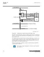
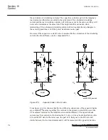
Figure 369:
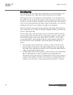
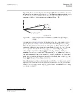
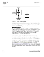
Circulating current caused by T1 on a higher tap than T2.
The circulating current I
cc
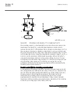
is predominantly reactive due to the reactive nature of the
transformers. The impact of I
cc
on the individual transformer currents is that it
increases the current in T1 (the transformer that is driving I
cc
) and decreases it in T2 at
the same time as it introduces contradictive phase shifts, as can be seen in figure
.
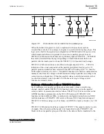
The result is thus, that the line voltage drop compensation calculated voltage V
L
for T1
will be higher than the line voltage drop compensation calculated voltage V
L
for T2, or
in other words, the transformer with the higher tap position will have the higher V
L
value and the transformer with the lower tap position will have the lower V
L
value.
Consequently, when the busbar voltage increases, T1 will be the one to tap down, and
when the busbar voltage decreases, T2 will be the one to tap up. The overall
performance will then be that the runaway tap situation will be avoided and that the
circulating current will be minimized.
Parallel control with the circulating current method
SEMOD159053-159 v5
Two transformers with different turns ratio, connected to the same busbar on the HV-
side, will apparently show different LV-side voltage. If they are now connected to the
same LV busbar but remain unloaded, this difference in no-load voltage will cause a
circulating current to flow through the transformers. When load is put on the
transformers, the circulating current will remain the same, but now it will be
superimposed on the load current in each transformer. Voltage control of parallel
transformers with the circulating current method means minimizing of the circulating
current at a given voltage target value, thereby achieving:
Section 15
1MRK 504 163-UUS A
Control
768
Transformer protection RET670 2.2 ANSI
Application manual
Summary of Contents for RELION RET670
Page 1: ...RELION 670 SERIES Transformer protection RET670 Version 2 2 ANSI Application manual ...
Page 2: ......
Page 48: ...42 ...
Page 64: ...58 ...
Page 74: ...68 ...
Page 104: ...98 ...
Page 194: ...188 ...
Page 518: ...512 ...
Page 618: ...612 ...
Page 648: ...642 ...
Page 666: ...660 ...
Page 672: ...666 ...
Page 682: ...676 ...
Page 844: ...838 ...
Page 868: ...862 ...
Page 956: ...950 ...
Page 964: ...958 ...
Page 1004: ...998 ...
Page 1014: ...1008 ...
Page 1015: ...1009 ...

