M13046-1 v12
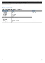
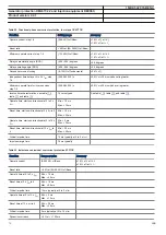
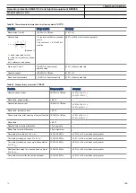
Table 40. Transformer differential protection T2WPDIF/T3WPDIF
Function
Range or value
Accuracy
Operating characteristic
Adaptable
±1.0% of Ir at I ≤ Ir
±1.0% of I at I > Ir
Reset ratio
> 90%
-
Unrestrained differential current limit
(100-5000)% of
IBase on high voltage
winding
±1.0% of set value
Minimum pickup
(5-60)% of IBase
±1.0% of Ir
Second harmonic blocking
(5.0-100.0)% of fundamental
differential current
±1.0% of I
r
Note: fundamental magnitude = 100% of I
r
Fifth harmonic blocking
(5.0-100.0)% of fundamental
differential current
±5.0% of I
r
Note: fundamental magnitude = 100% of I
r
Connection type for each of the
windings
Y or D
-
Phase displacement between high
voltage winding, W1 and each of the
windings, W2 and W3. Hour notation
0–11
-
*Operate time at 0 to 10 x IdMin,
restrained function
Min. = 25 ms
Max. = 35 ms
-
*Reset time at 10 x IdMin to 0,
restrained function
Min. = 5 ms
Max. = 15 ms
-
*Operate time at 0 to 10 x Idunre,
unrestrained function
Min. = 5 ms
Max. = 15 ms
-
*Reset time at 10 x Idunre to 0,
unrestrained function
Min. = 15 ms
Max. = 30 ms
-
**Operate time, unrestrained negative
sequence function
Min. = 10 ms
Max. = 20 ms
-
**Reset time, unrestrained negative
sequence function
Min. = 10 ms
Max. = 30 ms
-
Critical impulse time
2 ms typically at 0 to 5 x IdMin
-
*Note: Data obtained with single input current group.
**Note: Data obtained with two input current groups. The rated symmetrical currents are applied on both sides as pre- and after-fault currents.
The fault is performed by increasing one phase current to double on one side and decreasing same phase current to zero on the other side.
1MRK 502 074-BEN A
Generator protection REG670 2.2 and Injection equipment REX060,
REX061, REX062
Product version: 2.2.1
62
ABB


