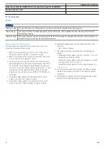
BOM/IOM/SOM should be activated
continuously due to power dissipation.
M12584-1 v7
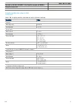
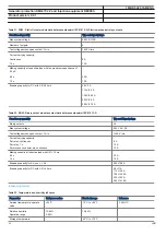
Table 19. IOM with MOV and IOM 220/250 V, 110mA - contact data (reference standard: IEC 61810-2)
Function or quantity
Trip and Signal relays
Fast signal relays (parallel reed relay)
Binary outputs
IOM: 10
IOM: 2
Max system voltage
250 V AC, DC
250 V DC
Test voltage across open
contact, 1 min
250 V rms
250 V rms
Current carrying capacity
Per relay, continuous
Per relay, 1 s
Per process connector pin,
continuous
8 A
10 A
12 A
8 A
10 A
12 A
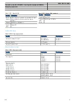
Making capacity at inductive
loadwith L/R > 10 ms
0.2 s
1.0 s
30 A
10 A
0.4 A
0.4 A
Making capacity at resistive load
0.2 s
1.0 s
30 A
10 A
220–250 V/0.4 A
110–125 V/0.4 A
48–60 V/0.2 A
24–30 V/0.1 A
Breaking capacity for AC, cos
j
> 0.4
250 V/8.0 A
250 V/8.0 A
Breaking capacity for DC with
L/R < 40 ms
48 V/1 A
110 V/0.4 A
220 V/0.2 A
250 V/0.15 A
48 V/1 A
110 V/0.4 A
220 V/0.2 A
250 V/0.15 A
Maximum capacitive load
-
10 nF
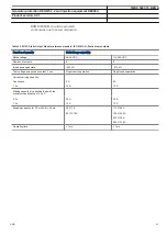
Maximum 72 outputs may be activated
simultaneously with influencing factors
within nominal range. After 6 ms an
additional 24 outputs may be activated.
The activation time for the 96 outputs must
not exceed 200 ms. 48 outputs can be
activated during 1 s. Continued activation
is possible with respect to current
consumption but after 5 minutes the
temperature rise will adversely affect the
hardware life. Maximum two relays per
1MRK 502 074-BEN A
Generator protection REG670 2.2 and Injection equipment REX060,
REX061, REX062
Product version: 2.2.1
52
ABB


