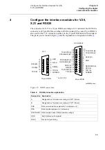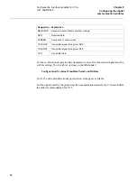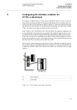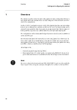
52
Configuring the short range fibre optical
modem
&KDSWHU
&RQILJXULQJWKHGLJLWDO
FRPPXQLFDWLRQPRGXOHV
The jumpers are accessible after the modem has been pulled out. This is done by first
removing all green 18-pin connectors at the back, then remove all screws holding the
back plate. After the back plate has been removed the modem can be pulled out.
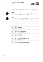
There are also some indication for supervision of the communication channel that can
be seen when the cover around the fibre optic connectors is removed. These LED’s are
found above the DIP-switches. The function of the LED’s are explained in table
7DEOH
,QGLFDWLRQV
1RWH
2QO\SXOORXWWKHPRGHPQRWWKHZKROHGRXEOHVL]H(XURFDUG$IWHUWKHMXPSHUVHWWLQJV
KDVEHHQFKDQJHGSXWHYHU\WKLQJEDFNLQUHYHUVHRUGHU
1RWH
$OOHOHFWURQLFDUHVHQVLWLYHWRHOHFWURVWDWLFGLVFKDUJH3URSHUDFWLRQPXVWEHWDNHQDW
WKHZRUNSODFHWRDYRLGHOHFWURVWDWLFGLVFKDUJH'LVFRQQHFW'&
/('
&RORU
([SODQDWLRQ
RTS
Yellow
Request to send
CTS
Yellow
Clear to send
DSR
Yellow
Data communication correct
DCD
Yellow
Detection of carrier signal
TXD
Yellow
Transmitted data
RXD
Yellow
Received data
RA
Red
Remotely detected problem with link
MA
Red
Memory function for problem with link
LO
Green
Link operation correctly
LA
Red
Locally detected problem with link
Sync
Green
Used when synchronization is selected
Summary of Contents for REL 531
Page 16: ...10 Note signs KDSWHU 6DIHW LQIRUPDWLRQ ...
Page 44: ...38 Checking the binary I O circuits KDSWHU KHFNLQJ WKH H WHUQDO FLUFXLWU ...
Page 52: ...46 Checking the self supervision signals KDSWHU QHUJLVLQJ WKH WHUPLQDO ...
Page 140: ...134 Testing the interaction of the distance protection KDSWHU 7HVWLQJ WKH SURWHFWLRQ V VWHP ...

