


2TLC172213M0201, rev. B
20 www.abb.com/jokabsafety
Step 12 – Test run the door
Place the door in the half open position by using the crank. Then remove the crank and connect the electrical
supply to the door.
•
Push the “OPEN ” (S21) button (if fitted) on the control panel. Stop the door immediately by pushing the
“STOP” button (S22).
-
If the door is moving upwards the phases are connected correct.
-
If the door moves downwards two phases have to change places on the connection blocks (1, 2, 3).
•
Always finally adjust the limit position cams in small steps to ensure that the door does not go past its end
positions and is damaged. Disconnect all external “OPEN” signals. Release the emergency stop but be
prepared to stop the door if necessary.
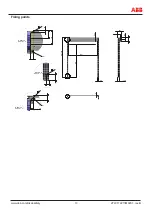
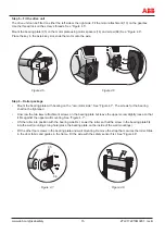
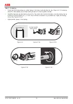
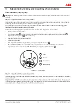
Step 13 – Adjustment of Eden sensors
•
Push the “CLOSE ” (S23) button on the control panel to close the door.
•
Adjust both adjustment plates (34) until the door’s guide rails (25) rest in the bottom of both the fork brackets
(30). The locking head (32) is mounted on the guide fitting’s right or left sides. See ”Figure 6.2”.
•
Adjust the Eden ADAM sensor (41) so that it is positioned opposite the Eden EVA sensor at a distance of no
more than 8 mm. See ”Figure 6.3”.
•
Check that the two parts of the Eden sensor cannot physically collide when the door is manoeuvred up or
down.
•
Manoeuvre the door to its end positions several times and check that the safety equipment receives a signal
when the door is in its closed position.
•
Mount the front frame cover (19/22)
32
41
25
30
2-8 mm
Figure 6.2
Figure 6.3
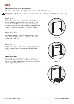
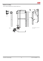
Step 14 – Fronts
•
Lift the front (02) into position and screw it against the bearing plates’ collar.
•
Mount the motor cover (01) on the motor, and wall (03) on the non-motor side.
•
Install the cable duct protection and decorative moulding (38) for the frame cover.