


www.abb.com/jokabsafety 19
2TLC172213M0201, rev. B
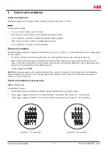
6
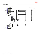
Adjustments, testing and mounting of cover plates
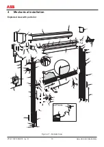
Final installation, step-by-step
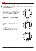
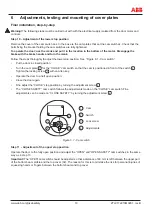
Step 10 – Adjustment of the lower stop position
Remove the cover of the cam switch box. In the box are the cam plates that set the cam switches. Check that the
bolts fixing the bracket holding the cam switches are fully tightened.
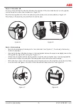
To operate the door; use the crank and put it in the location in the bottom of the motor. Disengage the
brake with the brake handle and turn the crank.
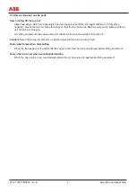
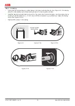
Follow the steps thoroughly to adjust the lower stop position. See ”Figure 6.1 - Cam switch”.
•
Put the door in closed position.
•
Turn the cam plate
1
for the “CLOSE” cam switch so that the cam is positioned in front of the switch
2
.
Tighten the locking screw
3
with an Allen key.
•
Operate the door to a half open position.
•
Close the door again.
•
Fine adjust the “CLOSE” stop position by turning the adjustment screw
4
.
•
The “CLOSE SAFETY” cam switch follows the adjustments made on the “CLOSE” cam switch. Fine
adjustments can be made on “CLOSE SAFETY” by turning the adjustment screw
4
.
3
2
1
4
1
2
3
4
Cam
Switch
Lock screw
Adjustments
Figure 6.1 - Cam switch
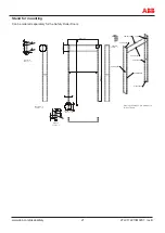
Step 11 – Adjustment of the upper stop position
Operate the door to the fully open position and adjust the “OPEN” and “OPEN SAFETY” cam switches in the same
way as in step 10.
Important!
The “OPEN” cam switch should be adjusted so that a distance of 60 mm is left between the upper part
of the bottom beam profile and the top cover (02). The reason for this is to minimize the risk for personal injuries of
squeezing hands or fingers between the bottom beam and top cover.
Warning!
The following steps must be carried out with with the electrical supply isolated from the door motor and
controls.