


2TLC172213M0201, rev. B
14 www.abb.com/jokabsafety
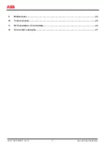
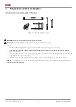
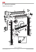
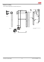
Mounting instructions, step by step
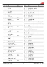
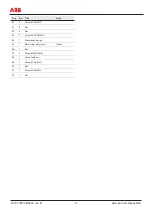
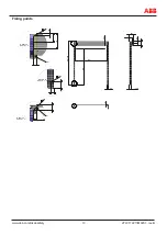
All position numbers refer to the exploded view. See ”Figure 4.1 - Exploded view”.
Warning!
Follow the instructions precisely when mounting the door. Not doing so runs the risk of the door falling
down with personal injuries as a result.
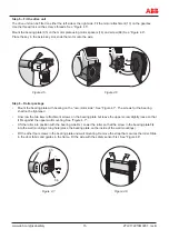
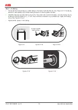
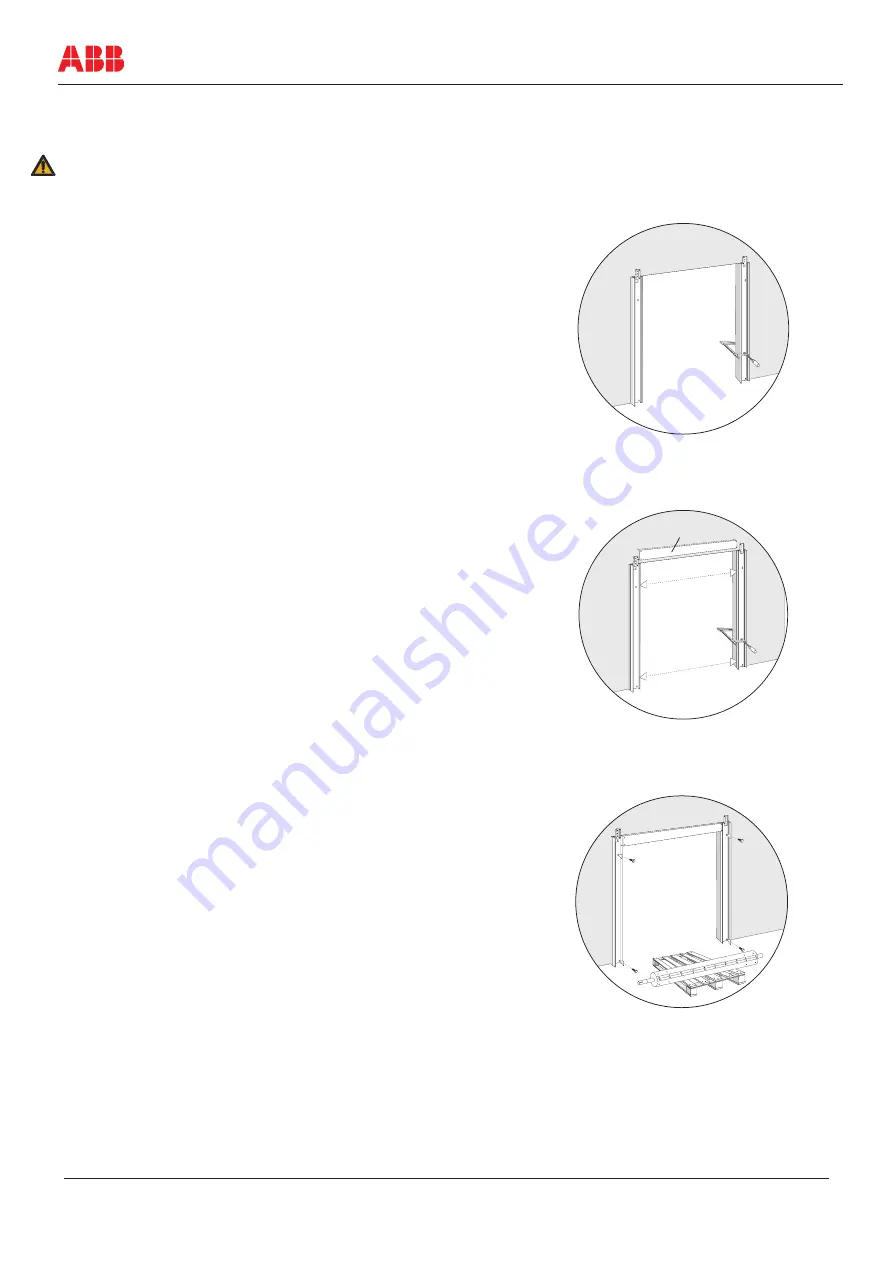
Step 4 – Attachment
The lower holes require a long drill (150 mm). Screw the door
tight in the wall. Use the pre-drilled holes and at least M10
screws in the upper wall attachments (09/15) and the lower wall
attachments (36/40). See ”Figure 4.4”.
Step 3 – Aligning
Align the door using a spirit level or an aligning instrument and
check that the top seal is horizontal and that the frames are
vertical.
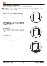
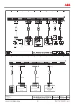
Step 2 – Back Plate
Mount the back plate (17) against the wall mountings’ upper
edge. The back plate determines the distance between the
frames. See ”Figure 4.3”.
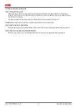
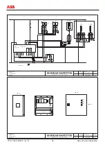
Step 1 – Frame
Remove the cover profiles 19 and 22 from frame profiles 10
and 20. Raise both frames, right and left respectively (10/20),
against the wall on the respective sides of the door opening
and attach them temporarily with the help of screw clamps. See
”Figure 4.2”. Protect the frame profiles to prevent scratches.
17
Figure 4.3
20
10
Figure 4.2
Figure 4.4