www.abb.com/jokabsafety 17
2TLC172213M0201, rev. B
5
Electrical installation
Cable requirements
Electrical supply via 5 conductor cable, 3 phase, neutral, ground (min 1.5 mm
2
).
Cable
Colour marked cables
•
4 core (1.5 mm
2
) cable + earth for motor
•
8/10 core (0.75 mm
2
) cable for cam switches and safety circuits
•
4 core (0.50 mm
2
) cable for contact strip. (Spiral Cable supplied)
•
6/8/10 core (0.50 mm
2
) cable for up/down/stop controls
•
4 core (0.50 mm
2
) cable for machine interface
Electrical conditions
Electrical supply needed for the Safety Roller Door is 3 phase, 3 x 400V or 3 x 230V. Motors for other voltage levels
can be ordered.
•
The drive unit has an electromagnetic brake, oil-cooled gearbox, thermo fuse and built in cam-box.
•
Motor and connection blocks are protected according to IP54. Always use screw caps that preserve the IP
class. (If the door is mounted in such a position that the drive unit could be affected by rain or wash-down then
the motor should be fitted with an additional cover).
•
Control voltage is
24 VDC
.
Electrical installation, step-by-step
Step 8 – Drive unit
Connecting the motor:
•
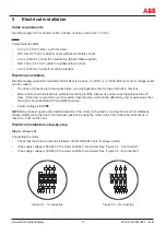
Check that the motor is marked as follows: 360-415/208-240 Volt. (3-phase system)
•
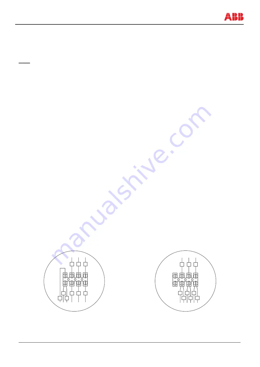
If the supply voltage is 360-425 V the motor shall be Y-connected. See ”Figure 5.1 - Y-connection”.
•
If the supply voltage is 208-240 V the motor shall be D-connected. See ”Figure 5.2 - D-connection”.
1
2
3
U2
V2
W2
U1
V1
W1
Y U V W
1
2
3
U2
V2
W2
U1
V1
W1
Y U V W
Figure 5.1 - Y-connection
Figure 5.2 - D-connection
NB!
Before phase sequence (the rotation direction of the motor) is checked by running the door short distances,
always initially, place the door in an half open position by using the motor crank. Then follow the instructions in
”Step 12 – Test run the door”.

