


Modifications reserved
Page 40/50
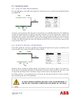
Situation of UPS-System before starting the Transfer Procedure to Maintenance Bypass:
The load is protected by PowerWave 33 running in normal operation. (The UPS is operating on
inverter).
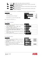
1.
Using LCD panel, select the COMMANDS menu, choose command “LOAD TO
BYPASS” and transfer the load to mains. (for parallel operation is enough to give the
order in one of the units).
2.
Close Maintenance Bypass Switch IA1 (position ON). On a system with multiple UPS in
parallel close IA1 on each UPS.
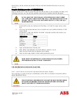
3.
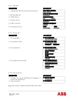
The message “MANUAL BYP IS CLOSED” will appear on the LCD and the mimic panel
will show as below:
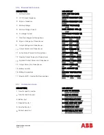
LED Indicator
Colour
LINE 1
Green
LINE 2
Green
BYPASS
Green
INVERTER
RED
BATTERY
Green
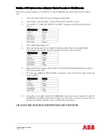
4.
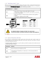
Press simultaneously the two ON/OFF buttons on the UPS-control panel (PMD) on all
control panels.
On the LCD’s message “LOAD OFF, SUPPLY FAILURE” will appear and the mimic panel
will show:
LED Indicator
Colour
LINE 1
Green
LINE 2
OFF
BYPASS
OFF
INVERTER
OFF
BATTERY
Green
5.
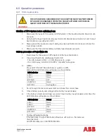
Open the Output Switch IA2, Input Switch IA4 and Bypass Switch IA3 on all UPSs
6.
Open battery fuses/breakers on the external battery cabinets or racks.
NOTE
THE UPS SYSTEM IS STILL POWERED (DANGEROUS VOLTAGE).
6.5.4
Load Transfer: from Maintenance Bypass to Inverter operations
This procedure describes the sequence of operations to be done in order to restart the UPS and
restore ON-LINE mode (Load on Inverter).
WARNING!
THE OPERATIONS DESCRIBED IN THIS CHAPTER MUST BE PERFORMED
BY A SERVICE ENGINEER FROM THE MANUFACTURER OR FROM AN
AGENT CERTIFIED BY THE MANUFACTURER.
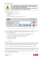
Summary of Contents for PowerWave 33 Series 3
Page 1: ... Copyright 2017 ABB All rights reserved User Manual PowerWave 33 Series 3 60 120 kW ...
Page 46: ...Modifications reserved Page 46 50 10 Attachments 10 1 Technical data sheet ...
Page 48: ......
Page 49: ... Copyright 2016 ABB All rights reserved Technical data sheet PowerWave 33 Serie 3 60 120 kW ...