Modifications reserved
Page 21/50
5
Connectivity
5.1
Customer interface
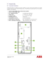
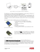
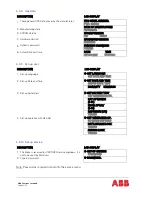
Each UPS cabinet is provided with customer interface ports (also called communication ports) which
provides information about the UPS (single units) or the UPS system (parallel system). The customer
interface is composed by:
1.
Slot for optional USB & relay card (customer outputs)
2.
Slot for optional SNMP card
3.
PC / laptop connection
JD1 (RS232 Sub D9/female)
4.
Status LED’s
1 red LED and 1 green LED
5.
Customer inputs
X1 1-10 Phoenix terminals
6.
Multidrop connector
JR2 (RJ 45)
7.
Parallel BUS connector
JD1 (Sub D25/female)
8.
Multi-Cabinet Configuration
SW1-9 (DIP-SWITCH), see chapter 6.2.3
9.
SW2 – Multidrop configuration
SW2 (DIP-SWITCH), see chapter 6.2.4
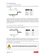
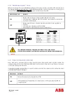
Figure 15: Overview of the customer interface.
3
2
1
4
5
6
9
8
7
Summary of Contents for PowerWave 33 Series 3
Page 1: ... Copyright 2017 ABB All rights reserved User Manual PowerWave 33 Series 3 60 120 kW ...
Page 46: ...Modifications reserved Page 46 50 10 Attachments 10 1 Technical data sheet ...
Page 48: ......
Page 49: ... Copyright 2016 ABB All rights reserved Technical data sheet PowerWave 33 Serie 3 60 120 kW ...


