IB 6.1.12.1-1C
1
9
ABB
A
Torque
Hinge Joint
Contact Pressure
Adjustment Gap
Transfer Contact
Member
Pushrod
Insulator
Yoke
A
Contact Pressure
Adjustment Gap
Torque
Hinge Joint
Arc Runner
Assy
Moving Arc
Contact Member
Adjustment
Stud
Upper Terminal
Current Studs
(Upper & Lower
Halves)
Moving Main
Contact Member
Upper Terminal
(stab portion)
Stationary Arc
Contact Member
Moving Arc
Contact Member
A
Adjustment Stud
Arc Runner Assy
Moving Main
Contact Member
Stationary Main Contact
(Upper Terminal)
Stationary Main Contact
(Lower Terminal)
Contact Pressure
Increase
Contact Pressure
Decrease
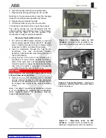
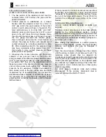
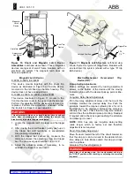
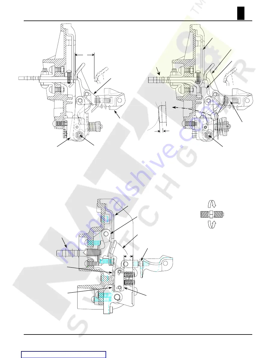
Figure 6a. 225 Ampere Contact Structure.
Left-hand
view drawn in the closed position. Similar structure to
Figure 6b, except the moving arc contact member
serves as the moving main contact member. Notice that
the upper terminal is comprised of one stud. Contact
pressure is established by open-air gap
A
.
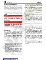
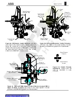
Figure 6b. 600 and 800 Ampere Contact Structure.
Left-hand view, drawn in the closed position. Contact
pressure is established by gap
A
on a closed breaker.
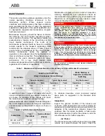
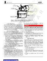
Figure 6c. 1600 and 2000 Ampere Contact Structure (except 2000 A
Upper Terminal).
Left-hand view drawn in the closed position. Contact
pressure is established with gap
A
on a closed breaker.
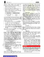
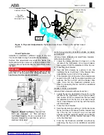
Figure 6d. Contact Pressure
Adjustment.
Viewed from left
side as illustrated in each
structure.

