IB 6.1.12.1-1C
2
7
ABB
Appendix A
General Circuit Breaker Information
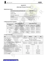
Table A1 – Test Voltages for AC Dielectric Withstand-Voltage Test
Secondary (Control) Circuit
Primary Circuit
Motor Disconnected
Motor Connected
Circuit Breaker
Condition
[V
AC
]
[V
AC
]
[V
AC
]
New
2200 1500 1000
In-Service
(75% of New)
1500 1125 750
After Short-Circuit
(60% of New
)
1320 900 600
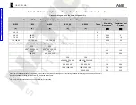
Table A2 - Control Circuit Requirements at Standard Voltages
Charging Circuit
Close Circuit
Shunt Trip Circuit
Average Motor
Current
Control Relay Coil
Current
Nominal Control
Voltage
Ametek
Ryobi
Operating
Range
Anti-Pump
Release
Operating
Range
Coil
Current
Recommended
Control Fuse
Rating
[V @ f]
[A]
[A]
[V]
[A]
[A]
[V]
[A]
[A]
120 V
AC
@ 50/60 Hz
10
4
104-127
0.15 1.5
104-127
6.5
10
240 V
AC
@ 50/60 Hz
5
2
208-254
0.075 0.75
208-254
1.15
10
48 V
DC
25
10
38-56
0.11
1.26
28-56
3.14 15
125 V
DC
10
4
100-140
0.054
0.69
70-140
1.3 10
250 V
DC
5
2
200-280
0.026
0.38
140-280
0.65 10
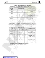
Table A3 - Undervoltage Trip Device Operating Conditions
Reference IB 6705 for Field Installation Instructions
Nominal Control
Voltage
Current at
Nominal
Voltage
Maximum
Pickup Voltage
(80% of Nominal)
Dropout
Voltage Range
(30-60% of
Nominal)
[V @ f]
[A]
[V]
[V]
120 V
AC
@ 50/60 Hz
0.5
96
36-72
240 V
AC
@ 50/60 Hz
0.2
192
72-144
480 V
AC
@ 50/60 Hz
0.1
384
144-288
48 V
DC
0.3 38 15-29
125 V
DC
0.2 100 38-75
250 V
DC
0.1 200
75-150

