


Note
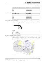
Article number
Equipment, etc.
-
Standard toolkit
Article number is specified in
section
-
Technical reference manual - System
parameters
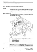
Installation, mechanical stops axis 1
Use this procedure to fit the additional mechanical stops to axis 1 of the robot. An
assembly drawing is also enclosed with the product.
Note
Action
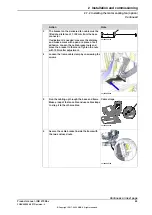
DANGER
Turn off all:
•
electric power supply to the robot
•
hydraulic pressure supply to the robot
•
air pressure supply to the robot
Before entering the robot working area.
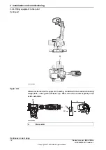
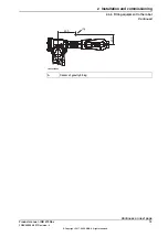
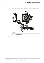
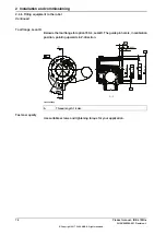
1
Tightening torque: 60 Nm.
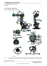
Fit the additional mechanical stop to the
frame according to the figure
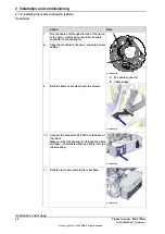
2
The system parameters that must be
changed (
Upper joint bound
and
Lower
joint bound
) are described in
Technical
reference manual - System parameters
.
Adjust the software working range limitations
(system parameter configuration) to corres-
pond to the mechanical limitations.
3
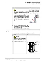
WARNING
If the mechanical stop pin is deformed after
a hard collision, it must be replaced!
Deformed
movable stops
and/or
additional
stops
as well as deformed
attachment
screws
must also be replaced after a hard
collision.
4
Product manual - IRB 6700Inv
81
3HAC058254-001 Revision: L
© Copyright 2017 - 2020 ABB. All rights reserved.
2 Installation and commissioning
2.5.2 Mechanically restricting the working range of axis 1
Continued
Summary of Contents for IRB 6700Inv
Page 1: ...ROBOTICS Product manual IRB 6700Inv ...
Page 16: ...This page is intentionally left blank ...
Page 40: ...This page is intentionally left blank ...
Page 182: ...This page is intentionally left blank ...
Page 672: ...This page is intentionally left blank ...
Page 704: ...This page is intentionally left blank ...
Page 720: ...This page is intentionally left blank ...
Page 722: ...This page is intentionally left blank ...
Page 729: ......


