


4 Repair
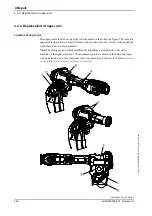
4.3.5. Replacement of complete arm system
235
3HAC020993-001 Revision: G
©
Co
py
rig
h
t 200
4-
200
8 ABB. All righ
ts reser
v
ed.
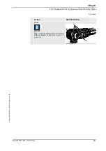
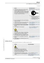
8. Remove the guide pins and secure the arm
system to the base with its 24
attachment
screws and washers.
Shown in the figure
M12 x 110, 12.9 quality UNBRAKO.
Tightening torque: 110 Nm.
Reused screws may be used, providing
they are lubricated as detailed in section
before fitting.
9. Refit the
block for calibration
at the bottom of
the frame.
Shown in the figure
10. Refit the motor axis 1.
Detailed in section
.
Detailed in section
.
11. Refit the cabling in the base.
12. Perform a leak-down test of the gearbox axis
1.
Detailed in section
13. Refill the gearbox axis 1 with lubricating oil.
Detailed in section
.
14. Recalibrate the robot.
Calibration is detailed in a separate
calibration manual, enclosed with the
calibration tools.
General calibration information is
included in section
.
15.
DANGER!
Make sure all safety requirements are met
when performing the first test run. These are
further detailed in section
test run may cause injury or damage! on
page 38
Action
Note/Illustration
Continued


