4 Repair
4.4.3. Replacement of upper arm
3HAC020993-001 Revision: G
254
©
Co
py
rig
h
t 200
4-
200
8 ABB. All righ
ts reser
v
ed.
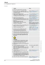
5. In order to release the brake of the axis 3 motor,
connect the 24 VDC power supply, after
removing the motor cover.
Connect to connector R2.MP3
•
+: pin 2
•
-: pin 5
6. Fasten the
lifting tool (chain)
onto the lifting eye,
the lifting device and an overhead crane.
Art. no. is specified in
!
7.
CAUTION!
The complete upper arm weighs 380 kg without
any additional equipment fitted! Use a suitable
lifting device to avoid injury to personnel!
8. Lift the upper arm and move to its mounting
position.
Make sure the lift is done completely level!
9. Fit in the gearbox attachment holes with the
attachment holes on the lower arm with the
guide pins.
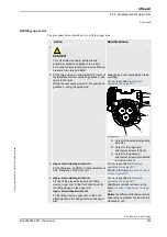
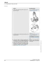
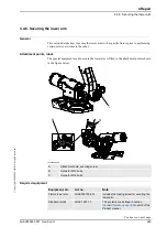
It may be necessary to turn the gear by rotating
the motor pinion with a
rotation tool, motor
beneath the motor cover.
Art. no. is specified in
!
xx0200000165
The rotation tool is used beneath the
motor cover, directly on the motor shaft
as shown in figure above.
•
A: Rotation tool
10. Fit the three
washers
to be placed beneath the
attachment screws.
Shown in the figure
!
11. Insert 31 of the 33
attachment screws, upper
arm
into the attachment holes in the lower arm.
Do not remove the guide pins until the
attachment screws are tightened as detailed
below.
Shown in the figure
!
Removing the plastic mechanical stops
may be required before fitting the upper
arm.
If guide pins are removed before the
screws are tightened, the sealing can
be involuntarily moved into wrong
position.
12. Secure the lower arm to gearbox axis 3, with
the attachment screws.
33 pcs: M12 x 50; 12.9 quality
UNBRAKO, tightening torque: 120 Nm.
Reused screws may be used, providing
they are lubricated as detailed in
section
before fitting.
13. Remove the guide pins and fit the two
remaining attachment screws. Tighten them as
detailed above!
Action
Note/Illustration
Continued
Continues on next page


