


3 Maintenance
3.3.13. Inspection, position switch axes 1, 2 and 3
3HAC020993-001 Revision: G
148
©
Co
py
rig
h
t 200
4-
200
8 ABB. All righ
ts reser
v
ed.
3.3.13. Inspection, position switch axes 1, 2 and 3
Position switches, axes 1-3
The position switches are shown, fitted to the robot, in section
.
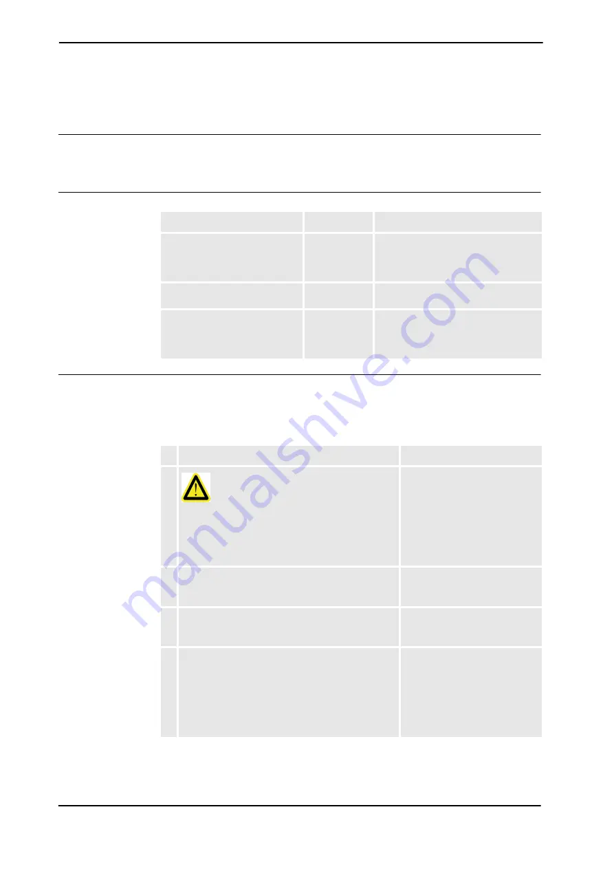
Required equipment
Inspection, position switches
The procedure below details how to inspect the position switch, axes 1, 2 and 3.
See the figures in section
Installation of position switches (option) on page 92
to locate the
different components to be inspected.
Equipment, etc.
Art. no.
Note
Position switch, axes 1-3
-
The article numbers of the position
switches are specified in section
lation of position switches (option) on
page 92
.
Standard toolkit
-
The contents are defined in section
.
Other tools and procedures may
be required. See references to
these procedures in the step-by-
step instructions below.
These procedures include references to
the tools required.
Action
Note
1.
DANGER!
Turn off all electric power, hydraulic and pneumatic
pressure supplies to the robot!
For Foundry Prime robots: Do not turn off the air
pressure to motors and SMB.
2. Check the position switch!
•
Check that the rollers are easy to push in and
that they roll freely.
3. Check the rail!
•
Check that the rail is firmly attached with the
attachment screws.
4. Check the cams!
•
Check that the rollers have not caused any
impressions on the cams.
•
Check that the cams are clean. Wipe them if
necessary!
•
Check that the set screws holding the cams in
position are firmly attached.
Continues on next page


