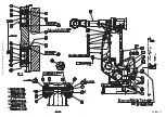
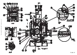
background image

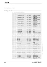
7 Part list

7.1. Introduction

281

 3HAC022032-001  Revision: E     

© Copyri

ght 

200

4-2008 ABB.

 All rights reserved.

7 Part list

7.1. Introduction

Overview

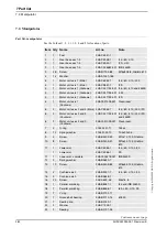
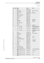
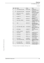
This section specifies all the replacement articles of the robot. The parts are shown in 

exploded views or in foldouts, either in this or in a separate chapter.

Specific spare parts are listed separately in a Spare part list.

Summary of Contents for IRB 4400 - 45

Page 1: ...Product manual Articulated robot IRB 4400 45 IRB 4400 60 IRB 4400 L10 IRB 4400 L30 IRB 4400 LS IRB 4400 45 M2000 M2000A M2004 ...

Page 2: ......

Page 3: ... Copyright 2004 2008 ABB All rights reserved Product manual IRB 4400 45 IRB 4400 60 IRB 4400 L10 IRB 4400 L30 IRB 4400 S IRB 4450S M2000 M2004 Document ID 3HAC022032 001 Revision E ...

Page 4: ...sons or property fitness for a specific purpose or the like In no event shall ABB be liable for incidental or consequential damages arising from use of this manual and products described herein This manual and parts thereof must not be reproduced or copied without ABB s written permission and contents thereof must not be imparted to a third party nor be used for any unauthorized purpose Contravent...

Page 5: ...e the information on safety and information labels 29 1 3 Safety related instructions 30 1 3 1 Safety signals general 30 1 3 2 DANGER Moving manipulators are potentially lethal 32 1 3 3 DANGER First test run may cause injury or damage 33 1 3 4 WARNING The unit is sensitive to ESD 34 1 3 5 WARNING Safety risks during work with gearbox oil 36 2 Installation and commissioning 37 2 1 Introduction 37 2...

Page 6: ...02 3 4 4 Oil change gearbox axis 5 and 6 all robot versions except IRB 4400 L10 105 3 4 5 Oil change gearbox axis 5 and 6 IRB 4400 L10 only 108 4 Repair 111 4 1 Introduction 111 4 2 General procedures 112 4 2 1 Performing a leak down test 112 4 2 2 Mounting instructions for bearings 113 4 2 3 Mounting instructions for seals 114 4 3 Complete robot 116 4 3 1 Replacement of cable harness axes 1 3 116...

Page 7: ...n information 235 5 1 Introduction 235 5 2 Calibration methods 236 5 3 Calibration scales and correct axis position 238 5 4 Calibration movement directions for all axes 240 5 5 Updating revolution counters 241 5 6 Checking the calibration position 245 5 7 Additional calibration instruction IRB4400 247 Overview 249 Product documentation M2000 M2000A 251 Product documentation M2004 252 6 Reference i...

Page 8: ...Table of Contents 6 3HAC022032 001 Revision E Copyright 2004 2008 ABB All rights reserved ...

Page 9: ...tion personnel maintenance personnel repair personnel Prerequisites A maintenance repair installation craftsman working with an ABB Robot must be trained by ABB and have the required knowledge of mechanical and electrical installation repair maintenance work Organization of chapters The manual is organized in the following chapters Chapter Contents Safety service Safety information Installation an...

Page 10: ... 2 Changes made in the material from the previous manuals Model M2004 implemented A Chapter Safety service replaced with chapter Safety Chapter Calibration replaced with chapter Calibration information Removed chapter Calibration M2004 B Yaskawa motors been added C Robot model IRB 4450S added D Foundry Prime Water jet application added E Cleanroom added Changes made in Prerequisites in section Ove...

Page 11: ... calibration decommissioning Product manual reference information Reference information article numbers for documentation referred to in Product manual procedures lists of tools safety standards Part list Foldouts or exploded views Circuit diagrams The product manual published as a PDF consists of only one file where the two parts are presented together as one Product manual Software manuals The s...

Page 12: ...tallation electrical connections Maintenance descriptions of all required preventive maintenance procedures including intervals Repair descriptions of all recommended repair procedures including spare parts Additional procedures if any calibration decommissioning Product manual reference information Reference information article numbers for documentation referred to in Product manual procedures li...

Page 13: ...pplication what it does and when it is useful What is included e g cables I O boards RAPID instructions system parameters CD with PC software How to use the application Examples of how to use the application Operating manuals This group of manuals is aimed at those having first hand operational contact with the robot i e production cell operators programmers and trouble shooters The group of manua...

Page 14: ...ude references to equipment spare parts tools etc required for the different actions in the procedure The equipment is marked with italic text in the procedures and completed with a reference to the section where the equipment is listed with further information i e article number dimension The denomination in the procedure for the component or attachment point corresponds to the denomination in th...

Page 15: ... to attend to before performing any service work on the robot These are applicable for all service work and are found in section General safety information on page 14 specific safety information pointed out in the procedure at the moment of the danger How to avoid and eliminate the danger is either detailed directly in the procedure or further detailed in separate instructions found in section Saf...

Page 16: ...ial robot described in the applicable documents e g User s Guide S4Cplus M2000 Operating Manual IRC5 with FlexPendant M2004 Product Manual Connection of external safety devices Apart from the built in safety functions the robot is also supplied with an interface for the connection of external safety devices Via this interface an external safety function can interact with other machines and periphe...

Page 17: ... be crossed before admittance must be set up in front of the robot s working space Light beams or sensitive mats are suitable devices Turntables or the like should be used to keep the operator out of the robot s working space The axes are affected by the force of gravity when the brakes are released In addition to the risk of being hit by moving robot parts you run the risk of being crushed by the...

Page 18: ...collapse of robot Take any necessary measures to ensure that the robot does not collapse as parts are removed e g secure the lower arm with fixtures if removing motor axis 2 Safety risk Description Cable packs are sensitive to mechanical damage The cable packs are sensitive to mechanical damage They must be handled with care especially the connectors in order to avoid damaging them Safety risk Des...

Page 19: ... to safely turn off tools such as milling cutters etc Make sure that guards remain closed until the cutters stop rotating It should be possible to release parts by manual operation valves Safe design Grippers end effectors must be designed so that they retain workpieces in the event of a power failure or a disturbance of the controller Ensure that a gripper is prevented from dropping a workpiece i...

Page 20: ... to pneumatic and hydraulic systems Residual energy Residual energy may be present in these systems After shutdown particular care must be taken The pressure in pneumatic and hydraulic systems must be released before starting to repair them Safe design Gravity may cause any parts or objects held by these systems to drop Dump valves should be used in case of emergency Shot bolts should be used to p...

Page 21: ...rried out professionally and in accordance with the applicable safety regulations Care must be taken at all times Qualified personnel Corrective maintenance must only be carried out by qualified personnel who are familiar with the entire installation as well as the special risks associated with its different parts Extraordinary risks If the working process is interrupted extra care must be taken d...

Page 22: ...side the robot s working space Voltage related risks controller S4Cplus A danger of high voltage is associated with the following parts Be aware of stored electrical energy DC link in the controller Units inside the controller e g I O modules can be supplied with power from an external source The mains supply mains switch The power unit The power supply unit for the computer system 230 VAC The rec...

Page 23: ...VAC The service outlets 115 230 VAC The customer power supply 230 VAC The power supply unit for additional tools or special power supply units for the machining process The external voltage connected to the controller remains live even when the robot is disconnected from the mains Additional connections Voltage related risks robot A danger of high voltage is associated with the robot in The power ...

Page 24: ...sion the fence or enclosure to enable it to withstand the force created if the load being handled by the robot is dropped or released at maximum speed Determine the maximum speed from the maximum velocities of the robot axes and from the position at which the robot is working in the work cell see Product Specification Description Robot Motion Also consider the maximum possible impact caused by a b...

Page 25: ...e extinguishing 23 3HAC022032 001 Revision E Copyright 2004 2008 ABB All rights reserved 1 2 3 2 Fire extinguishing Use a CARBON DIOXIDE CO2 extinguisher in the event of a fire in the robot system manipulator or controller ...

Page 26: ...ke release buttons on the robot How to release the brakes is detailed in section Manually releasing the brakes on page 54 Manually releasing the brakes in the product manual for the robot The robot arm may be moved manually on smaller robot models but larger models may require using an overhead crane or similar Increased injury Before releasing the brakes make sure that the weight of the arms does...

Page 27: ...ction How to test The function of the holding brake of each axis motor may be checked as detailed below 1 Run each manipulator axis to a position where the combined weight of the manipulator arm and any load is maximized max static load 2 Switch the motor to the MOTORS OFF position with the Operating mode selector on the controller 3 Check that the axis maintains its position If the manipulator do...

Page 28: ... 001 Revision E 26 Copyright 2004 2008 ABB All rights reserved 1 2 3 5 Risk of disabling function Reduced speed 250 mm s Do not change Transm gear ratio or other kinematic system parameters from the FlexPendant or a PC This will affect the safety function Reduced speed 250 mm s ...

Page 29: ...leased or pushed all the way in the robot is taken to the MOTORS OFF state To ensure safe use of the FlexPendant the following must be implemented The enabling device must never be rendered inoperative in any way During programming and testing the enabling device must be released as soon as there is no need for the robot to move The programmer must always bring the FlexPendant with him her when en...

Page 30: ...l panel The robot s speed is limited to max 250 mm s when the operating mode selector is in position manual mode with reduced speed This should be the normal position when entering the working space The position manual mode with full speed 100 may only be used by trained personnel who are aware of the risks that this entails Pay attention to the rotating axes of the manipulator Keep a distance to ...

Page 31: ...e product contain space for adding a fourth language underneath the three standard languages English German and French Add a local language to the label by Using a transparent sticker over the standard label with text added in a fourth language Drawings detailing the design text figure dimensions of the standard labels can be ordered from ABB Notice that each label is identified according to the a...

Page 32: ...h for example contact with high voltage electrical units explosion or fire risk risk of poisonous gases risk of crushing impact fall from height etc warning WARNING Warns that an accident may occur if the instructions are not followed that can lead to serious injury possibly fatal and or great damage to the product It applies to warnings that apply to danger with for example contact with high volt...

Page 33: ...lectrostatic discharge ESD symbol indicates electrostatic hazards which could result in severe damage to the product Note NOTE Note symbols alert you to important facts and conditions Tip TIP Tip symbols direct you to specific instructions where to find additional information or how to perform a certain operation in an easier way Symbol Designation Signification Continued ...

Page 34: ...ination Action Note 1 Before attempting to run the manipulator make sure all emergency stop equipment is correctly installed and connected Emergency stop equipment such as gates tread mats light curtains etc 2 If possible use the hold to run function whenever possible The hold to run function is used in manual mode not in automatic mode How to use the hold to run function in RobotWare 5 0 is detai...

Page 35: ...ks to take into consideration before the first test run Elimination Follow the procedure below when performing the first test run after a service activity repair installation or maintenance Action 1 Remove all service tools and foreign objects from the robot and its working area 2 Install all safety equipment properly 3 Make sure all personnel are standing at a safe distance from the robot i e out...

Page 36: ...ay potentially transfer high static charges This discharge may destroy sensitive electronics Elimination Location of wrist strap button The wrist strap button is located in the top right corner as shown in the illustration below xx0500002171 Action Note 1 Use a wrist strap Wrist straps must be tested frequently to ensure that they are not damaged and are operating correctly 2 Use an ESD protective...

Page 37: ...B All rights reserved Assemble the wrist strap The picture illustrates how the ESD wrist strap is assembled in the controller xx0400001055 A The strap is fastened to a button on the side of the control module B When not used the wrist strap is placed on the power supply unit C Power supply unit Continued ...

Page 38: ...e opening Do not overfill the gearbox when filling Do not overfill Overfilling of gearbox oil can lead to internal over pressure inside the gearbox which in turn may damage seals and gaskets completely press out seals and gaskets preventthemanipulator from moving freely Make sure not to overfill the gearbox when filling with oil After filling check the correct oil level Do not mix types of oil Mix...

Page 39: ...erved 2 Installation and commissioning 2 1 Introduction General This chapter contains information for installing the robot to the working site More detailed technical data such as load diagram permitted extra loads equipment and location of extra loads equipment may be found in the Product Specification for the robot ...

Page 40: ...f the robot is not to be installed directly it must be stored as described in Storage conditions robot on page 41 5 Make sure the expected operating environment of the robot conforms to the specifications as described in Operating conditions robot on page 41 6 Before taking the robot to the installation site make sure the site conforms to Loads on foundation robot all versions except IRB 4400 S an...

Page 41: ...d during operation The values also never reach their maximum at the same time The rigidity of the foundation must be designed to minimize the affects of dynamic behaviour on the robot For optimal performance the frequency for the foundation bearing the robot must be higher than 30 Hz TuneServo can be used to adapt robot tuning for a non optimal foundation Fxy and Mxy are vectors that can have any ...

Page 42: ...ustration below shows the directions of the stress forces xx0500002108 This table shows stress forces for the robot version IRB 4450S Loads on foundation robot version IRB 4400 S xx0300000255 Force Endurance load in operation Max load emergency load Force xy 7500 N 10000 N Force z 9500 2000 N 9500 4000 N Torque xy 14000 Nm 16000 Nm Torque z 2000 Nm 4000 Nm Continued Continues on next page ...

Page 43: ... Force x 5000 N 7000 N Force y 6000 9000 N Force z 10 000 5000 N 10 000 7000 N Torque x 8500 Nm 11 500 Nm Torque y 3500 14 000 Nm 3500 11 500 Nm Torque z 6500 Nm 11 000 Nm Force x 5000 5000 N 5000 7000 N Force y 6000 N 9000 N Force z 8500 3000N 8500 5500 N Torque x 9500 Nm 12 000 Nm Torque y 3500 7500 Nm 3500 11 500 Nm Torque z 2000 Nm 5500 Nm Parameter Value Min ambient temperature 25 C Max ambie...

Page 44: ... motion The table below specifies the types and ranges of the robot motion in every axis Pos no Position X mm Position Z mm Angle Axis 2 degrees Angle Axis 3 degrees 0 1080 1720 0 0 1 887 2140 0 30 2 708 836 0 65 3 1894 221 95 60 4 570 126 95 40 5 51 1554 70 40 6 227 1210 70 65 Location of motion Type of motion Range of movement Axis 1 Rotation motion 165 to 165 Axis 2 Arm motion 95 to 70 Axis 3 A...

Page 45: ...elow specifies the types and ranges of the robot motion in every axis Positions in illustration Position X mm Position Z mm Angle Axis 2 degrees Angle Axis 3 degrees B 1580 1720 0 0 C 1320 2390 0 30 D 919 383 0 65 E 2303 66 95 60 F 180 448 95 42 G 484 1804 70 40 H 725 1254 70 65 Location of motion Type of motion Range of movement Axis 1 Rotation motion 165 to 165 Axis 2 Arm motion 95 to 70 Axis 3 ...

Page 46: ...low specifies the types and ranges of the robot motion in every axis Position in illustration Position X mm Position Z mm Angle Axis 2 degrees Angle Axis 3 degrees B 1700 1720 0 0 C 1424 2450 0 30 D 970 274 0 65 E 2401 135 95 60 F 500 786 95 23 6 G 588 1864 70 40 H 845 1265 70 65 Location of motion Type of motion Range of movement Axis 1 Rotation motion 165 to 165 Axis 2 Arm motion 95 to 70 Axis 3...

Page 47: ... specifies the types and ranges of the robot motion in every axis Positions in illustration Position X mm Position Z mm Angle Axis 2 degrees Angle Axis 3 degrees B 1580 1720 0 0 C 1320 2390 0 30 D 919 383 0 65 E 2360 120 90 60 F 239 417 90 44 G 484 1804 70 40 H 725 1254 70 65 Location of motion Type of motion Range of movement Axis 1 Rotation motion 135 to 135 Axis 2 Arm motion 90 to 70 Axis 3 Arm...

Page 48: ...d ranges of the robot motion in every axis Positions in illustration Position X mm Position Z mm Angle Axis 2 degrees Angle Axis 3 degrees B 2006 556 0 0 C 2190 978 0 30 D 1101 239 0 65 E 1437 1054 95 60 F 294 303 95 40 G 1195 1208 70 40 H 1058 847 70 65 570 390 530 645 1176 2400 X Z C D G H F E B Location of motion Type of motion Range of motion Axis 1 Rotation motion 135 to 135 Axis 2 Arm motion...

Page 49: ...is not stable in the whole working area Moving the arms will displace the center of gravity which may cause the robot to tip over Do not change the robot position before securing it to the foundation Stability The figure below shows the robot in its shipping position which also is the most stable position xx0500002035 The robot is likely to be mechanically unstable while not secured to the foundat...

Page 50: ...d equipment The manipulator weighs 1300 kg All lifting equipment used must be dimensioned accordingly Personnel must not under any circumstances be present under the suspended load Failure to attach the straps correctly can cause the suspended load to tilt suddenly and cause both personal injury and severe damage to the load Equipment Art no Note Crane Lifting capacity 2100kg max load at 90 Round ...

Page 51: ... 4400 45 60 L10 L30 A Angle degrees specified for the different versions in the lifting instruction B Lifting lug Action Info Illustration 1 Release the brakes manually to make it possible to alter the positions of the arms Detailed in section Manually releasing the brakes on page 54 2 Move the robot to the calibration position 3 Move the lower arm backwards to get balance according to angle speci...

Page 52: ...nd 3 using lifting lugs Shown in the figure Lifting robot version IRB 4400 45 60 L10 L30 on page 49 The roundsling and lifting lug dimensions must comply with the applicable standards specified in Required equipment on page 48 5 Lift the robot to its installation site Make sure the slings do not rub against any sharp edges Action Info Illustration 1 Lifting angle for the robot 0 2 Lifting angle fo...

Page 53: ...to angle specified to the right Angle A is shown in the figure Lifting robot version IRB 4400 S on page 50 If the robot liftangle is 0 then A 25 30 then A 0 4 Attach the round slings to the special eye bolts on the gearbox unit for axes 2 and 3 using lifting lugs If the lifting angle of the robot is more than 0 a round sling must also be attached to the rear of the robot Attachment points are show...

Page 54: ...d for the different versions in the lifting instruction B Mechanical stop Action Info Illustration 1 Release the brakes manually to make it possible to alter the positions of the arms Detailed in section Manually releasing the brakes on page 54 2 Move the robot to its shipping position See figure Lifting robot version IRB 4450S on page 52 3 Move the robot to the calibration position 4 Move the low...

Page 55: ...ach the round slings around the mechanical stop as a third lifting point Attachment points are shown in figure xx0500002035 above The roundsling and lifting lug dimensions must comply with the applicable standards specified in 6 Lift the robot to its installation site Make sure the slings do not rub against any sharp edges 7 Danger When the robot is put down before attachment to the floor is done ...

Page 56: ...ly directly on the respective brake When releasing the holding brakes the manipulator axes may move very quickly and sometimes in unexpected ways Make sure no personnel is near the manipulator arm Using the pushbutton when the robot is connected to the controller The procedure below details how to release the holding brakes with pushbuttons when the robot is connected to the controller Action Info...

Page 57: ...ternal 24VDC power supply to the connector R1 MP on the robot base as shown in the figure to the right Note Be careful not to interchange the 24V and 0V pins If they are mixed up damage can be caused to the brake release unit and the system board Danger DANGER Incorrect connections can cause all brakes to be released simultaneously xx0300000200 Connect to connector R1 MP 0V pin B14 or B15 24V pin ...

Page 58: ...brake Action Note Illustration 1 Every axis has a holding brake built into the axis motor This holding brake may be released by connecting 24VDC power supply directly to one of the connectors in the motor Danger DANGER When power is connected directly to the brake cable the brake will be released immediately when the power is switched This may cause some unexpected robot movements Make the connect...

Page 59: ...acts The table below specifies the type of securing screws and washers to be used to secure the robot to the base plate foundation Securing parts fact Dimension art no Amount Note Securing screws oiled M20 3 pcs Washers Thickness 3 mm Outer diameter 36 mm Inner diameter 21 mm 3 pcs Guide sleeves 2151 0024 169 2 pcs Added to the rear bolt holes to allow the same robot to be re mounted without progr...

Page 60: ...the foundation The manipulator weighs 1300 kg All lifting equipment used must be dimensioned accordingly A Rear bolt holes B Center line axis 1 Action Info Illustration 1 Warning When the robot is put down before attachment to the floor is done the risk of tipping is big if not properly secured 2 Lift the robot Detailed in section Lifting robot with round slings on page 48 3 Move the robot to the ...

Page 61: ...n Securing parts facts on page 57 Attachment holes shown in the figure Hole configuration and dimensions on page 58 7 When bolting a mounting plate or frame to a concrete floor follow the general instructions for expansion shell bolts The screw joint must be able to withstand the stress loads defined in section Loads on foundation robot all versions except IRB 4400 S and 4450S on page 39 Action In...

Page 62: ...L30 S and IRB 4450S The illustration below shows the mounting holes available for fitting extra equipment on the upper arm for robot versions IRB 4400 45 60 L30 S and IRB 4450S The shaded area indicates the permitted positions center of gravity for any extra equipment mounted in the holes xx0300000264 E Max 15 kg F M8 2x holes used if option 043 is chosen Depth of thread 9 mm G M8 3x Depth of thre...

Page 63: ... The illustration below shows the mounting holes available for fitting extra equipment on the upper arm for robot versions IRB 4400 L10 The shaded area indicates the permitted positions center of gravity for any extra equipment mounted in the holes xx0300000265 C Max 15 kg D M6 2x Depth of thread 9 mm E M8 3x Depth of thread 14 mm F Max 2 kg G M5 2x Continued Continues on next page ...

Page 64: ...ny extra equipment mounted in the holes xx0300000266 Fitting equipment on gearbox unit IRB 4450S The illustration below shows the mounting holes available for fitting extra equipment on the gearbox unit The shaded area indicates the permitted positions center of gravity for any extra equipment mounted in the holes xx0500002136 A M8 3x R 2 Depth 16 mm if option 623 is chosen these holes are occupie...

Page 65: ...IRB 4400 45 60 L30 S and IRB 4450S The illustration below shows the mechanical interface for the mounting flange robot version IRB 4400 45 60 L30 S and IRB 4450S xx0300000267 Fitting equipment on mounting flange IRB 4400 10 The illustration below shows the mechanical interface for the mounting flange robot version IRB 4400 L10 xx0300000268 C The hole can go through Continued ...

Page 66: ...ements and overloading the motors Incorrect defined loads may result in operational stops or major damage in bearings References Load diagrams permitted extra loads equipment and their positions are specified in the Product Specification The loads must also be defined in the software as detailed in User s Guide RobotWare 4 0 Operating manual RobotWare 5 0 Stop time and braking distances Robot moto...

Page 67: ...it may collide with other objects its working space should be limited The working range of the following axes may be restricted Axis 1 hardware mechanical stop and software signal from adjustable position switch Axis 2 hardware mechanical stop Axis 3 software signal from limit switch This section describes how to install hardware that restricts the working range Notice that adjustments must also b...

Page 68: ...ion Required equipment Equipment etc Spare part no Art no Note Mechanical stop axis 1 3HAB 3833 1 Includes 2 additional stop lugs 8 attachment screws 8 plain washers and a label Attachment screw 9ADA 183 71 4 pcs lug included in 3HAB 3833 1 M12x60 Washer 9ADA 312 9 4 pcs lug included in 3HAB 3833 1 13x24x2 5 Standard toolkit 3HAC 17594 1 The contents are defined in section Standard toolkit on page...

Page 69: ...sion E Copyright 2004 2008 ABB All rights reserved Additional stops The additional stops are fitted as shown in the figure below xx0300000258 B Mechanical stop lugs C Attachment screw and washer D Stop pin E Max working range with stop lugs 250 F Min working range with stop lugs 127 Continued Continues on next page ...

Page 70: ... are also supplied with the kit Action Info Illustration 1 Determine the position of the stop lugs and mark the hole positions on the base See the figure Additional stops on page 67 for guidance 2 Drill Ø10 2 mm to a maximum depth of 45 mm and tap with M12 thread Min thread depth 35 mm 3 Fit the stop lugs firmly with attachment screws and washers according to the figure Additional stops on page 67...

Page 71: ...ers and dampers to the lower arm and gearbox unit axis 1 3 as detailed in this section Required equipment Equipment etc Spare part no Art no Note Mechanical stop axis 2 3HAC 4225 1 Includes spacers dampers attachment screws and nuts Spacer damper 3HAB 9185 1 Spacer 3HAC 3962 1 Standard toolkit 3HAC 17594 1 The contents are defined in section Standard toolkit on page 264 Other tools and procedures ...

Page 72: ... ABB All rights reserved Additional stops The additional mechanical stops spacers and dampers are fitted to the lower arm and the gearbox unit as shown in the figure below xx0300000260 A View A of the lower arm B View B of the lower arm C Cut of the mech stop attachment D Spacer E Attachment screw spacer nut Continued Continues on next page ...

Page 73: ...onal mechanical stop to the lower arm and the gearbox unit Mounting instructions are also supplied with the kit F Damper G Attachment screw damper nut Working range Damper qty Spacer qty 95 70 95 40 2 95 10 2 2 65 70 2 65 40 2 2 65 10 4 2 35 70 4 35 40 4 2 35 10 6 2 5 70 not applicable on IRB 4400 S 6 5 40 not applicable on IRB 4400 S 6 2 5 10 not applicable on IRB 4400 S 8 2 Action Info Illustrat...

Page 74: ...ight 2004 2008 ABB All rights reserved 3 Fit the dampers to both sides of the lower arm with the attachment screws and nuts damper Shown in the figure Additional stops on page 70 Art no is specified in Required equipment on page 69 Attachment screws 2 pcs damper M10x60 Tightening torque 49 Nm Action Info Illustration Continued ...

Page 75: ... senses the current position via a cam Electrical stop All the separate parts of the electrical stop are fitted to axis 3 as shown in the figure below xx0300000262 A Sealing with dust lip 3HAB 3701 14 B Stud 2122 2012 867 C All screws are locked with locking liquid D Tap 3HAB 3798 1 E Hexagon nut 9ADA 267 7 F Disc 3HAB 3799 1 G Screw 9ADA 618 44 H Cam 3HAB 3800 1 I Bracket 3HAB 8400 1 J Limit swit...

Page 76: ...ical stop on page 73 Locking liquid Loctite 243 Standard toolkit 3HAC 17594 1 The contents are defined in section Standard toolkit on page 264 Other tools and procedures may be required See references to these procedures in the step by step instructions below These procedures include references to the tools required Circuit Diagrams See chapter Circuit diagram in the Product manual reference infor...

Page 77: ...axis 4 should be removed Follow the procedure below to dismantle the mechanical stop A more detailed view of the component and its position may be found in chapter Foldouts in the Product manual reference information Location of mechanical stop axis 4 The mechanical stop of axis 4 is located as shown in the figure below A more detailed view of the component and its position may be found in chapter...

Page 78: ...can be damaged when the function Resetting the work area for an axis is used or if the robot is jogged uncalibrated Action Info Illustration 1 Turn off all electric power hydraulic and pneumatic pressure supplies to the robot For Foundry Prime robots Do not turn off the air pressure to motors and SMB 2 Loosen the attachment screws mech stop and remove the mechanical stop axis 4 Shown in the figure...

Page 79: ...SH44N and one FCI UT071412SH44N connector on the rear part of the upper arm The customer connections are located on the robot as shown in the figure below xx0300000270 Extra equipment connections Connections to the air hose R1 4 is located on the rear part of the upper arm and at the base Max 8 bar Inner hose diameter 8 mm signal cabling option 042 are located on the front of the upper arm Number ...

Page 80: ...CP CS 3HAC 12275 1 socket for area of 0 14 0 5 mm2 compression gland for cables diameter 2 x 12 mm key pin Connection set R1 CP CS F IRB 4400 Protection Foundry R1 CP CS 3HAC 12276 1 socket for area of 0 14 0 5 mm2 compression gland for cables diameters 10 mm and 12 mm key pin Connection set R2 CS R3 CS R2 CS R3 CS 3HAC 12327 1 pins for cable area of 0 13 0 25 mm2 reduction hose bottled shaped red...

Page 81: ...of the arm xx0300000269 Power supply connections on upper arm A R2 CP B R2 CS C Signal lamp option D R3 H1 R3 H2 Signal name Customer Terminal Controller Customer Contact on Upper arm R2 Customer Contact on robot base cable between robot and con troller not supplied CPA XT6 1 R2 CP A RI CP CS A1 CPB XT6 2 R2 CP B RI CP CS B1 CPC XT6 3 R2 CP C RI CP CS C1 CPD XT6 4 R2 CP D RI CP CS D1 CPE XT6 5 R2 ...

Page 82: ...on robot base cable between robot and con troller not supplied CSA XT5 1 R2 CS A R1 CS CP B5 CSB XT5 2 R2 CS B R1 CS CP C5 CSC XT5 3 R2 CS C R1 CS CP D5 CSD XT5 4 R2 CS D R1 CS CP A6 CSE XT5 5 R2 CS E R1 CS CP B6 CSF XT5 6 R2 CS F R1 CS CP C6 CSG XT5 7 R2 CS G R1 CS CP D6 CSH XT5 8 R2 CS H R1 CS CP A7 CSJ XT5 9 R2 CS J R1 CS CP B7 CSK XT5 10 R2 CS K R1 CS CP C7 CSL XT5 11 R2 CS L R1 CS CP D7 CSM X...

Page 83: ...ng off an cleaning cell we recommend that the humid air inside a cell is ventilated out to avoid that the humid air is sucked into e g gearboxes due to the raised vacuum when cooled down Environmental conditions Air specification for pressurizing of robot The air must be dry and clean such as instrument air Following table details the air specification If the pressurized air contains oil it could ...

Page 84: ...xposed to direct or rebounding high pressure jet of water Protecting the wrist joints The sealings between the moving parts on the wrist should not be exposed to direct high pressure water We recommend that the gripper include a shield that prevents direct water flush on the sealing surfaces of the wrist The sealings are pointed out in the illustration below Action Note Illustration 1 Connect a co...

Page 85: ...e should be protected A Axis 5 bearing support side B Axis 5 bearing gear side C Axis 6 mounting flange gear house A B C Action Note Illustration 1 After mounting the tool clean the following surfaces from grease the visible surface not painted the rear end of the screw holes and end of screws xx0600003109 screw holes and screws unpainted surface 2 Protect these surfaces with Mercasol 3106 3 Befor...

Page 86: ...in motors and serial measurement compartment during cooling down of robot after it has been switched off To reduce the risk for corrosion due to condensation in gearboxes it is recommendable that the robot is running with high speed on each axes at least on one occasion each hour This is to lubricate the gearbox cavities When turning off an cleaning cell we recommend that the humid air is ventilat...

Page 87: ...ion from the robot For example some articles in the robot s design which normally are exposed to some wear during operation are unpainted If replaced these articles must be replaced with new unpainted ones Cleanroom class 5 Particle emission from the robot fulfill Cleanroom class 5 standard according to DIN EN ISO 14644 1 Preparations before commissioning a Cleanroom robot During transport and han...

Page 88: ...2 Installation and commissioning 2 7 1 Additional installation procedure 3HAC022032 001 Revision E 86 Copyright 2004 2008 ABB All rights reserved ...

Page 89: ...uding intervals and refers to procedures for the activities Each procedure contains all information required to perform the activity that is required tools and materials The procedures are gathered in different sections divided according to the maintenance activity Safety information Before any service work is commenced it is extremely important that all safety information is observed There are ge...

Page 90: ...ance intervals Description The intervals may be specified in different ways depending on the type of maintenance activity to be carried out and the working conditions of the robot Calendar time specified in months regardless of whether the robot system is run or not Operating time specified in operating hours More frequent running of the robot means more frequent maintenance activities ...

Page 91: ...nding on current conditions An alert is given on the TPU or the FlexPendant when the battery is nearly discharged and it must then be replaced within a month 2 The gearboxes are lubricated for life which corresponds to 40 000 hours of operation if the robot is operating with an ambient temperature of less than 40 C If the temperature is higher the oil should be changed 3 Must be replaced if bent M...

Page 92: ... must then be replaced within a month 2 The gearboxes are lubricated for life which corresponds to 40 000 hours of operation if the robot is operating with an ambient temperature of less than 40 C If the temperature is higher the oil should be changed 3 Must be replaced if bent 4 Parts that need to be changed according to the maintenance schedule are not covered by warranty Maintenance activity Eq...

Page 93: ... the frame as shown in the figure below xx0300000182 Required equipment A Mechanical stop pin axis 1 B Set screw Equipment etc Spare part no Art no Note Mechanical stop axis 1 3HAB 3647 1 Standard toolkit 3HAC 17594 1 The contents are defined in section Standard toolkit on page 264 Other tools and procedures may be required See references to these procedures in the step by step instructions below ...

Page 94: ...placed Action Info Illustration 1 Turn off all electric power hydraulic and pneumatic pressure supplies to the robot For Foundry Prime robots Do not turn off the air pressure to motors and SMB 2 Check regularly that the pin is not bent or damaged in any other way If bent damaged the pin must be replaced by a new one Removal refitting of the mechanical stop is detailed in section Replacement of mec...

Page 95: ...re gauge cut off valve Action Note Illustration 1 Apply compressed air to the air connector on robot base and raise the pressure with the knob until the correct value is shown on the pressure gauge Recommended pressure 0 2 0 3 bar xx0600003341 A Air Connection B Pressure gauge C Cut off valve 2 Close the cut off valve It should take at least 5 sec for the pressure to reach 0 bar 3 The time 5 sec T...

Page 96: ...n in the figure below must be removed xx0300000106 Required equipment A Rear cover plate Equipment etc Spare part no Art no Note Battery pack 4944 026 4 Rechargeable nickel cadmium battery Battery pack 3HAC 16831 1 Lithium battery Standard toolkit 3HAC 17594 1 The contents are defined in section Standard toolkit in the Product manual reference information Other tools and procedures may be required...

Page 97: ... the robot to the MOTORS OFF operating mode This way the robot does not need to be calibrated after the battery change 3 Remove the rear cover plate from the base Shown in the figure Location of battery pack on page 94 4 Loosen the battery terminals from the serial measuring board and cut the clasps that keep the battery pack in place 5 Remove the old battery pack 6 Fit a new battery pack with two...

Page 98: ...t Do s and don ts The section below specifies some special considerations when cleaning the robot Always Always use cleaning equipment as specified above Any other cleaning equipment may shorten the life of paintwork rust inhibitors signs or labels Always check that all protective covers are fitted to the robot before cleaning Never Never remove any covers or other protective devices before cleani...

Page 99: ... changed This section specifies the oil permitted in the unit Oil in gears IRB 4400 45 60 L30 L10 and IRB 4450S The lubricating oil specified above corresponds to Mobilegear 600 XP 320 Oil in gears IRB 4400 FS The lubricating oil specified above corresponds to Mobilegear 600 XP 320 Gear Art no Volume Note Axis 1 1171 2016 604 8 200 ml Axis 2 3 1171 2016 604 5 800 ml Gear Art no Volume Note Axis 1 ...

Page 100: ...ure below The figure shows the location of the axis 2 side and is the same on the opposite side Note The location of these oil plugs on the IRB 4450S is slightly different compared to the other robot versions xx0300000331 Location of oil plugs axis 4 The axis 4 gearbox has one oil plug for draining and one oil plug for filling located as shown in the figure below xx0300000220 A Oil plug filling A ...

Page 101: ...e below xx0300000223 Location of oil plugs axes 5 and 6 only IRB 4400 L10 The wrist unit has one oil plug for draining the oil and one oil plug for filling located as shown in the figure below The oil plug for filling is also used as an air inlet when draining the oil xx0300000118 A Oil plug draining 2 pcs the other oil plug not shown in figure B Oil plug filling also used for draining A Oil plug ...

Page 102: ... the manufacturer If the oils are mixed the gearbox must be thoroughly rinsed Contact ABB for further instructions Equipment etc Spare part no Art no Note Standard toolkit 3HAC 17594 1 The contents are defined in section Standard toolkit on page 264 Other tools and procedures may be required See references to these procedures in the step by step instructions below These procedures include referenc...

Page 103: ...e calibration position 2 Remove one of the oil plugs draining at the rear of the wrist Shown in the figure Location of oil plugs axes 5 and 6 all robot versions except IRB 4400 L10 on page 99 3 Required oil level on level with the edge of the oil plug hole 4 Fill with lubricating oil if necessary Type of oil is detailed in section Oil change gearbox axis 5 and 6 all robot versions except IRB 4400 ...

Page 104: ...uired equipment A Upper oil plug filling B Lower oil plug draining Equipment etc Spare part no Art no Note Lubricating oil 3HAC 0860 1 Optimol Optigear BM 100 Volume 3 400 ml Standard toolkit 3HAC 17594 1 The contents are defined in section Standard toolkit on page 264 Oil collecting vessel Capacity 4 000 ml Other tools and procedures may be required See references to these procedures in the step ...

Page 105: ... from the specified amount depending on how much oil has previously been drained from the gearbox When filling gearbox oil do not mix different types of oil as this may cause severe damage to the gearbox Always use the type of oil specified by the manufacturer If the oils are mixed the gearbox must be thoroughly rinsed Contact ABB for further instructions When filling gearbox oil do not overfill s...

Page 106: ... the upper oil plug filling Shown in the figure Location of oil plugs on page 102 3 Fill the gearbox with lubricating oil Amount and art no is specified in Required equipment on page 102 Correct oil level is specified in section Inspection of oil levels on page 98 4 Clean and refit the oil plug Action Note Illustration Continued ...

Page 107: ...x0300000223 Required equipment A Oil plug draining 2 pcs the other oil plug not shown in figure B Oil plug filling also used for draining Equipment etc Spare part no Art no Note Lubricating oil 3HAC 0860 1 Optimol Optigear BM 100 Volume 3 400 ml Standard toolkit 3HAC 17594 1 The contents are defined in section Standard toolkit on page 264 Oil collecting vessel Capacity 4 000 ml Other tools and pro...

Page 108: ...sure present in the gearbox causing oil to spray from the opening Action Info Illustration 1 Move the upper arm to a horizontal position and turn axis 4 to the calibration position 2 Turn axis 4 135 3 Remove the lower oil plug draining at the rear of the wrist Shown in the figure Location of oil plugs on page 105 Capacity of oil collecting vessel is specified in Required equipment on page 105 4 Re...

Page 109: ...e mixed the gearbox must be thoroughly rinsed Contact ABB for further instructions When filling gearbox oil do not overfill since this could lead to internal over pressure inside the gearbox which in turn may damage seals and gaskets completely press out seals and gaskets prevent the manipulator from moving freely Action Note Illustration 1 Move the upper arm to a horizontal position and turn axis...

Page 110: ...s an air inlet when draining the oil xx0300000118 Required equipment A Oil plug draining B Oil plug filling also used as air inlet when draining Equipment etc Spare part no Art no Note Lubricating oil 3HAC 0860 1 Optimol Optigear BM 100 Volume 800 ml Standard toolkit 3HAC 17594 1 The contents are defined in section Standard toolkit on page 264 Oil collecting vessel Capacity 1000 ml Other tools and...

Page 111: ...ld up in gearbox When opening the oil plug there may be pressure present in the gearbox causing oil to spray from the opening Action Info Illustration 1 Move the upper arm to a horizontal position and turn axis 4 to the calibration position 2 Remove the oil plug draining in the wrist Shown in the figure Location of oil plugs on page 108 3 Turn axis 4 to a position where the oil plug draining is fa...

Page 112: ...o the gearbox Always use the type of oil specified by the manufacturer If the oils are mixed the gearbox must be thoroughly rinsed Contact ABB for further instructions When filling gearbox oil do not overfill since this could lead to internal over pressure inside the gearbox which in turn may damage seals and gaskets completely press out seals and gaskets prevent the manipulator from moving freely...

Page 113: ...hered in sections divided according to the component location on the robot Required equipment All equipment required to perform a specific repair activity is listed together with the current procedure The equipment is also gathered in different lists in the Product manual reference information Safety information Before any service work is commenced it is extremely important that all safety informa...

Page 114: ...ay be required which are included in the leakdown tester kit Art no is specified above 3 Apply compressed air and raise the pressure with the knob until the correct value is shown on the manometer Recommended value 0 2 0 25 bar 20 25 kPa 4 Disconnect the compressed air supply 5 Wait for approx 8 10 minutes No pressure loss must be detected If the compressed air is signifi cantly colder or warmer t...

Page 115: ...able the roller elements to adjust to the correct position against the race flange 1 Tension the bearing gradually until the recommended pre tension is achieved Note The roller elements must be rotated a specified number of turns before pre tensioning is carried out and also rotated during the pre tensioning sequence 2 Make sure the bearing is properly aligned as this will directly affect the life...

Page 116: ...ver threads keyways etc Equipment etc Art no Note Grease 3HAB 3537 1 Used to lubricate the seals Action Note 1 Check the seal to ensure that the seal is of the correct type provided with cutting edge there is no damage to the sealing edge feel with a fingernail 2 Inspect the sealing surface before mounting If scratches or damage are found the seal must be replaced as it may result in future leakag...

Page 117: ... defective the parts may not be used because leakage could occur 2 Clean the surfaces properly and in accordance with ABB recommendations 3 Distribute the sealing compound evenly over the surface preferably with a brush 4 Tighten the screws evenly when fastening the flange joint Action Note 1 Ensure that the correct o ring size is used 2 Check the o ring for surface defects burrs shape accuracy et...

Page 118: ...view X X Note The figures show the robot model IRB 4400 But the basic principle of the location of the cable harness axes 1 3 for the IRB 4450S is similair Cables are longer though A more detailed view of the component and its position may be found in chapter Foldouts in the Product manual reference information xx0300000111 A Rear cover plate B Connectors at the base Connectors at the rear cover p...

Page 119: ... motor 3 R3 MP3 R3 FB3 G Cable guides in the middle of axis 1 H Protection plate Equipment etc Spare part no Art no Note Cable harness axes 1 3 3HAC5958 1 IRB 4400 all models except IRB 4450S Cable harness axes 1 3 3HAC 025479 001 IRB 4450S Gasket 3HAC 4432 1 Between the motor and the connection box axes 1 2 and 3 Replace if damaged Standard toolkit 3HAC 17594 1 The contents are defined in section...

Page 120: ...serial measurement unit Removal detailed in section Removal serial measurement unit on page 181 4 Loosen the connectors R1 MP1 R2 FB1 3 R2 BU R2 BU1 3 Also loosen the earth connections Shown in the figure Location of cable harness axes 1 3 on page 116 5 Cut all the ties around bundle 6 Remove the cable bracket inside the base 7 Remove the cable guides and the protection plate in the middle of axis...

Page 121: ...4 Reconnect the connectors in the motors 1 2 3 Shown in the figure Location of cable harness view X X on page 117 5 Refit the cable guide and the protection plate in the middle of axis 1 Shown in the figure Location of cable harness view X X on page 117 6 Secure the cabling with straps according to foldout 3 See the Foldouts in the Product manual reference information 7 Refit the cable bracket ins...

Page 122: ...evision E 120 Copyright 2004 2008 ABB All rights reserved 14 Make sure all safety requirements are met when performing the first test run These are further detailed in section DANGER First test run may cause injury or damage on page 33 Action Info Illustration Continued ...

Page 123: ...ng figure for the view X X A more detailed view of the component and its position may be found in chapter Foldouts in the Product manual reference information xx0300000111 A Rear cover plate B Connectors at the base Connectors at the rear cover plate R1 MP R1 SMB R1 CP CS customer connection R2 MP4 6 Brake release connectors R2 BU R2 BU1 3 R2 BU4 6 Connectors at serial measurement unit R2 SMB R2 F...

Page 124: ...s at motor 3 R3 MP3 R3 FB3 G Cable guides in the middle of axis 1 H Protection plate Equipment etc Spare part no Art no Note Cable harness axes 4 6 3HAC 8304 1 IRB 4400 all models except IRB 4450S Cable harness axes 4 6 3HAC 025480 001 IRB 4450S Gasket 3HAB 3676 1 3 pcs Between the motor and the connection box Replace if damaged Standard toolkit 3HAC 17594 1 The contents are defined in section Sta...

Page 125: ... hydraulic and pneumatic pressure supplies to the robot For Foundry Prime robots Do not turn off the air pressure to motors and SMB 2 Remove the cover ot the connection box for motors 4 5 6 3 Remove the rear cover plate Shown in the figure Location of cable harness axes 4 6 on page 121 4 Remove the serial measurement unit Detailed in section Removal serial measurement unit on page 181 5 Loosen the...

Page 126: ... the connectors and make the cabling easier to handle 11 Loosen the cable bracket inside the lower arm and undo the two screws Shown in the figure Location of cable harness axes 4 6 on page 121 12 Loosen the cable bracket at the upper arm Shown in the figure Location of cable harness axes 4 6 on page 121 13 Loosen all the connectors to the motors at the upper arm and customer connections if any Sh...

Page 127: ...re below details how to refit the cable harness to the axes 4 6 A Axis 4 motor A1 Connector R3 MP4 A2 Connector R3 FB4 B Axis 5 motor B1 Connector R3 MP5 B2 Connector R3 FB5 C Axis 6 motor C1 Connector R3 MP6 C2 Connector R3 FB6 D Protection plate E Cable strap indoor F cable strap outdoor Action Info Illustration 1 Turn off all electric power hydraulic and pneumatic pressure supplies to the robot...

Page 128: ...gure Location of cable harness axes 4 6 on page 121 8 Refit the cable bracket inside the lower arm Shown in the figure Location of cable harness axes 4 6 on page 121 9 Feed the cabling through the protection plate and down through the axis 1 Shown in the figure Location of cable harness view X X on page 122 10 Refit the cable brackets A between the gearboxes of axes 2 and 3 and strap the cabling x...

Page 129: ...ed in a separate calibration manual enclosed with the calibration tools General calibration information is included in section Calibration information on page 235 18 Make sure all safety requirements are met when performing the first test run These are further detailed in section DANGER First test run may cause injury or damage on page 33 Action Info Illustration Continued ...

Page 130: ...e component and its position may be found in chapter Foldouts in the Product manual reference information xx0300000143 Required equipment A Lower arm B Upper arm C Attachment screws and friction washers lower arm D Parallel arm E V ring between lower arm and gearbox axis 3 Equipment etc Spare part no Art no Note V ring 3HAB 3773 11 2 pcs On both sides of the lower arm in the frame Grease 3HAB 3537...

Page 131: ...ools required Calibration Pendulum Instruction General calibration information is included in section Calibration information on page 235 Equipment etc Spare part no Art no Note Action Info Illustration 1 Turn off all electric power hydraulic and pneumatic pressure supplies to the robot For Foundry Prime robots Do not turn off the air pressure to motors and SMB 2 The complete arm system weighs 232...

Page 132: ... 4400 The same position of the upper arm resting against the lower arm should be applied for the IRB 4450S 6 Unload the weight of the arm system with lifting slings and a crane 7 Remove the balancing device Detailed in section Replacement of balancing device on page 172 8 Remove the parallel arm Detailed in section Replacement of parallel arm Replacement of bearing on page 168 9 Remove the attachm...

Page 133: ...undry Prime robots Do not turn off the air pressure to motors and SMB 2 The complete arm system weighs 232 kg All lifting equipment used must be sized accord ingly 3 Check and grease both of the V rings in the frame Replace if damaged Part no is specified in Required equipment on page 128 4 Lift the arm system into mounting position Make sure the arms are properly secured to each other A as shown ...

Page 134: ...ng on page 170 8 Refit the balancing device Detailed in section Refitting of balancing device on page 177 9 Move the upper arm to a horizontal position 10 Refit the tie rod Detailed in section Refitting tie rod on page 166 11 Refit the cabling to the upper arm Detailed in section Refitting cabling axes 4 6 on page 125 12 Recalibrate the robot Calibration is detailed in a separate calibration manua...

Page 135: ...des the wrist unit and is located as shown in the figure below The figure shows the IRB 4400 A more detailed view of the component and its position may be found in chapter Foldouts in the Product manual reference information xx0300000129 A Upper arm B Connectors of motors axes 4 5 and 6 C Connection box upper arm D Calibration plate axis 3 E VK cover F KM nut G Screw H Bearing I Sealing ring J Sha...

Page 136: ...toolkit on page 264 Dismounting tool 3HAC 0163 1 Used to pull out the shaft Mounting tool 3HAB 1463 1 Used to fit the inner ring of the bearing Contains two separate parts De air tool 3HAC 8704 1 Used to evacuate air when refitting VK cover if the cover has no grooves for venting Other tools and procedures may be required See references to these procedures in the step by step instructions below Th...

Page 137: ... edge of the cover and bend it away Shown in the figure Location of upper arm on page 133 10 Undo the KM nuts Shown in the figure Location of upper arm on page 133 11 Remove the screws Shown in the figure Location of upper arm on page 133 12 Pull out the shaft with the dismounting tool Mark the shafts left and right Art no is specified in Required equipment on page 134 13 Remove the sealings and b...

Page 138: ...nt on page 134 xx0300000130 A Holding on tool B Press tool C Inner ring 8 Apply locking liquid on the threads of the KM nut Locking liquid specified in Required equipment on page 134 Shown in the figure Required equipment on page 134 9 Tighten the KM nut on the left side with torque 95 Nm in order to center the upper arm on the right side first with 105 Nm Then unscrew the KM nut and re tighten it...

Page 139: ...e connectors to motors axes 4 5 and 6 Shown in the figure Location of upper arm on page 133 15 Recalibrate the robot Calibration is detailed in a separate calibration manual enclosed with the calibration tools General calibration information is included in section Calibration information on page 235 16 Make sure all safety requirements are met when performing the first test run These are further d...

Page 140: ...s depending on robot version A more detailed view of the component and its position may be found in chapter Foldouts in the Product manual reference information xx0300000150 Required equipment A Wrist unit B O ring C Sealing surface between wrist unit and upper arm tube D Attachment screws and washers Equipment etc Spare part no Art no Note Wrist unit IRB 4400 45 60 L30 S and IRB 4450S 3HAB 8271 1...

Page 141: ...lkit 3HAC 17594 1 The contents are defined in section Standard toolkit on page 264 Measuring tool 3HAB 7887 1 Used when mounting the wrist unit to robot version IRB 4400 L10 Other tools and procedures may be required See references to these procedures in the step by step instructions below These procedures include references to the tools required Calibration Pendulum Instruction Art no is specifie...

Page 142: ...ry out only the following servicing repair work on this unit 3 Remove the attachment screws and washers A xx0300000148 Wrist unit on robot version IRB 4400 45 60 L30 S and IRB 4450S xx0300000149 Wrist unit on robot version IRB 4400 L10 4 Remove the wrist unit from the upper arm Action Info Illustration Action Info Illustration 1 Turn off all electric power hydraulic and pneumatic pressure supplies...

Page 143: ...x35 Tightening torque 41 Nm 5 Fill the wrist unit with oil Detailed in section Oil change gearbox axis 5 and 6 all robot versions except IRB 4400 L10 on page 105 6 Recalibrate the robot Calibration is detailed in a separate calibration manual enclosed with the calibration tools General calibration information is included in section Calibration information on page 235 7 Make sure all safety require...

Page 144: ... and pneumatic pressure supplies to the robot For Foundry Prime robots Do not turn off the air pressure to motors and SMB 2 Lubricate and fit the o ring to the wrist unit Part no is specified in Required equipment on page 138 Shown in the figure Location of wrist unit on page 138 3 Move the upper arm to a vertical position wrist side pointing upwards 4 Refit the wrist unit Do not tighten the attac...

Page 145: ...led in section Oil change gearbox axis 5 and 6 IRB 4400 L10 only on page 108 10 Recalibrate the robot Calibration is detailed in a separate calibration manual enclosed with the calibration tools General calibration information is included in section Calibration information on page 235 11 Make sure all safety requirements are met when performing the first test run These are further detailed in sect...

Page 146: ...douts in the Product manual reference information xx0300000183 Required equipment A Upper arm tube B Axis 4 housing Equipment etc Spare part no Art no Note Upper arm without wrist and motors 3HAC 17542 1 Foundry also used for standard Standard toolkit 3HAC 17594 1 The contents are defined in section Standard toolkit on page 264 Other tools and procedures may be required See references to these pro...

Page 147: ...ailed in section Removal of wrist unit 3 Remove the motors for axes 4 5 and 6 Detailed in section Removal of motor axes 4 5 and 6 on page 204 4 Remove the arm house unit Detailed in section Removal of complete upper arm 5 Fit the new arm house unit Part no is specified in Required equipment on page 144 6 Refit the wrist unit Detailed in section Replacement of wrist unit on page 138 7 Refit the mot...

Page 148: ...evision E 146 Copyright 2004 2008 ABB All rights reserved 9 Make sure all safety requirements are met when performing the first test run These are further detailed in section DANGER First test run may cause injury or damage on page 33 Action Info Illustration Continued ...

Page 149: ...hapter Foldouts in the Product manual reference information xx0300000176 Required equipment A Mechanical stop axis 4 B Damper axis 4 C Attachment screws mech stop Equipment etc Spare part no Art no Note Mechanical stop axis 4 3HAB 8856 1 Damper 3HAB 3760 1 Flange sealing 1234 0011 116 Loctite 574 Standard toolkit 3HAC 17594 1 The contents are defined in section Standard toolkit on page 264 Other t...

Page 150: ...t Action Info Illustration 1 Turn off all electric power hydraulic and pneumatic pressure supplies to the robot For Foundry Prime robots Do not turn off the air pressure to motors and SMB 2 Remove the mechanical stop by removing its attachment screws Shown in the figure Location of mechanical stop on page 147 3 Rotate axis 4 so that the damper is visible Remove the damper Shown in the figure Locat...

Page 151: ...ght 2004 2008 ABB All rights reserved 4 Fit the mechanical stop to the axis 4 with its attachment screws Shown in the figure Location of mechanical stop on page 147 Part no is specified in Required equipment on page 147 4 pcs M8x16 Tightening torque 24 Nm Action Note Illustration Continued ...

Page 152: ...Required equipment A Wrist bracket B Upper arm bracket C Front and rear cable holders D Plastic hose Equipment etc Spare part no Art no Note Customer connection axis 4 3HAC 8820 1 Includes signal power cabling necessary brackets holders etc Standard toolkit 3HAC 17594 1 The contents are defined in section Standard toolkit on page 264 Other tools and procedures may be required See references to the...

Page 153: ... upper arm Shown in the figure Location of signal cabling upper arm on page 150 3 Remove the front and rear cable holders from the tube shaft Shown in the figure Location of signal cabling upper arm on page 150 4 Disconnect the connectors at the rear of the upper arm Action Note Illustration 1 Turn off all electric power hydraulic and pneumatic pressure supplies to the robot For Foundry Prime robo...

Page 154: ...ded Note If the cables gets fully extended stop the rotation and let out more cable from the rear cable holder This is done by loosening the grey holders and pushing ot the cables by hand 7 Complete the rotation Note Do not tighten the rear cable holder leave it open 8 First fit the front cable holder around the tube shaft Run the black plastic hose through the foot of the holder Fit the rear cabl...

Page 155: ...e pulling 10 Adjust the length of the cables by pushing and pulling the cables through the inner holders which are still loose Note When axis 4 is moving no stretching of the cables should be felt 11 Tighten the holders by hand Do not use tools 12 Reconnect the connectors at the rear end of the upper arm 13 Connect the air hose 14 Secure the cables and air hose together with cable straps above the...

Page 156: ...Art no Note Standard toolkit 3HAC 17594 1 The contents are defined in section Standard toolkit on page 264 Measuring tool play IRB 4400 45 60 L30 S and IRB 4450S 3HAB 1611 6 Measuring tool play IRB 4400 L10 3HAB 6337 1 Other tools and procedures may be required See references to these procedures in the step by step instructions below These procedures include references to the tools required Action...

Page 157: ...erent load and distances for the different robot versions as specified to the right xx0300000186 Values for robot version IRB 4400 45 60 L30 S and IRB 4450S A Measuring tool play B 100mm C 140mm F 200N Values for robot version IRB 4400 L10 A Measuring tool play B 140mm C 85mm F 40N 5 Remove the load and set the dial indicator to zero Action Info Illustration Continued Continues on next page ...

Page 158: ...rsion IRB 4400 45 60 L30 S and IRB 4450S A Measuring tool play B 100mm C 140mm F 200N Values for robot version IRB 4400 L10 A Measuring tool play B 140mm C 85mm F 40N 7 Remove the load and measure the play by reading the dial indicator The maximum play allowed at the given distance from the center of axis 5 is for robot version IRB 4400 45 60 L30 S and IRB 4450S 0 20mm IRB 4400 L10 0 08mm Action I...

Page 159: ...ion Equipment etc Spare part no Art no Note Standard toolkit 3HAC 17594 1 The contents are defined in section Standard toolkit on page 264 Measuring tool play IRB 4400 45 60 L30 S and IRB 4450S 3HAB 1611 6 Measuring tool play IRB 4400 L10 3HAB 6337 1 Other tools and procedures may be required See references to these procedures in the step by step instructions below These procedures include referen...

Page 160: ...L30 S and IRB 4450S A Measuring tool play B 100mm m 20 kg Values for robot version IRB 4400 L10 A Measuring tool play B 140mm m 10 kg 4 Apply load F in one direction Note Different load and distances for the different robot versions as specified to the right xx0300000189 Values for robot version IRB 4400 45 60 L30 S and IRB 4450S A Measuring tool play B 100mm C 100mm F 100N Values for robot versio...

Page 161: ...sion IRB 4400 45 60 L30 S and IRB 4450S A Measuring tool play B 100mm C 100mm F 100N Values for robot version IRB 4400 L10 A Measuring tool play B 100mm C 150mm F 40N 7 Remove the load and measure the play by reading the dial indicator The maximum play allowed at the given distance B from the center of axis 6 is for robot version IRB 4400 45 60 L30 S and IRB 4450S 0 15mm IRB 4400 L10 0 2mm Action ...

Page 162: ...ower arm The lower arm is located as shown in the figure below The figure shows the IRB 4400 A more detailed view of the component and its position may be found in chapter Foldouts in the Product manual reference information xx0300000141 A Lower arm B Attachment screws and friction washers lower arm C Calibration plate axis 2 D Damper E Parallel arm Continues on next page ...

Page 163: ...3HAC 17594 1 The contents are defined in section Standard toolkit on page 264 Other tools and procedures may be required See references to these procedures in the step by step instructions below These procedures include references to the tools required Calibration Pendulum Instruction General calibration information is included in section Calibration information on page 235 Action Info Illustratio...

Page 164: ...er hydraulic and pneumatic pressure supplies to the robot For Foundry Prime robots Do not turn off the air pressure to motors and SMB 2 The lower arm weighs 68 kg All lifting equipment used must be sized accordingly 3 Move the damper and the calibration plate from the old to the new lower arm Part no is specified in Required equipment on page 161 4 Check and grease both V rings in the frame Replac...

Page 165: ...he cabling Detailed in section Refitting cabling axes 4 6 on page 125 12 Recalibrate the robot Calibration is detailed in a separate calibration manual enclosed with the calibration tools General calibration information is included in section Calibration information on page 235 13 Make sure all safety requirements are met when performing the first test run These are further detailed in section DAN...

Page 166: ...rod The tie rod is located as shown in the figure below Figure shows the IRB 4400 A more detailed view of the component and its position may be found in chapter Foldouts in the Product manual reference information xx0300000117 A Tie rod B Attachment screw C Washer D O ring E Sealing outside F Spherical roller bearing G Sealing inside Continues on next page ...

Page 167: ...ll out the tie rod alternately at the upper and lower end if the tie rod Press tool 3HAB 1598 1 Used to press in the spherical roller bearing Press tool p arm 3HAB 1529 1 2 pcs Used to press on the tie rod alternately at the upper and lower end of the tie rod Other tools and procedures may be required See references to these procedures in the step by step instructions below These procedures includ...

Page 168: ...aulic and pneumatic pressure supplies to the robot For Foundry Prime robots Do not turn off the air pressure to motors and SMB 2 If the bearings are to be replaced fit new spherical roller bearings and new sealings inside to the tie rod Use the press tool Part Art no is specified in Required equipment on page 165 3 Lift the tie rod to its mounting site Make sure the tie rod is refitted with the co...

Page 169: ...separate calibration manual enclosed with the calibration tools General calibration information is included in section Calibration information on page 235 9 Make sure all safety requirements are met when performing the first test run These are further detailed in section DANGER First test run may cause injury or damage on page 33 Action Info Illustration Continued ...

Page 170: ...rm The parallel arm is located on the robot as shown in the figure below The figure shows the IRB 4400 The bearing of the parallel arm is shown in the enlarged view A more detailed view of the component and its position may be found in chapter Foldouts in the Product manual reference information xx0300000128 A Parallel arm B Attachment screw C Washer D V ring on parallel arm E Bearing F Sealing Co...

Page 171: ...AB 3537 1 Used to lubricate the bearings and sealings Standard toolkit 3HAC 17594 1 The contents are defined in section Standard toolkit on page 264 Lifting tool 3HAB 1412 1 Used to lift the parallel arm Other tools and procedures may be required See references to these procedures in the step by step instructions below These procedures include references to the tools required Calibration Pendulum ...

Page 172: ...0 attachment screws and the washer that holds the parallel arm to gearbox axis 3 6 Lift away the parallel arm from the robot 7 If they are to be replaced remove the bearing and sealings from the parallel arm Action Info Illustration Action Info Illustration 1 Turn off all electric power hydraulic and pneumatic pressure supplies to the robot For Foundry Prime robots Do not turn off the air pressure...

Page 173: ... upper arm to a horizontal position with a crane if not already positioned horizontal and refit the tie rod Detailed in section Refitting tie rod on page 166 7 Reposition the cabling and tighten the cable attachment screws xx0300000127 8 Recalibrate the robot Calibration is detailed in a separate calibration manual enclosed with the calibration tools General calibration information is included in ...

Page 174: ...ancing device The balancing device is located as shown in the figure below The figure shows the IRB 4400 A more detailed view of the component and its position may be found in chapter Foldouts in the Product manual reference information xx0300000100 A Balancing device B Bracket C Attachment screws bracket M12x50 D Press out hole E Front screws F Fork G End part of shaft Continues on next page ...

Page 175: ...o lubricate the bearings at the balancing device brackets min 500 ml in each bearing the sealing at the balancing device brackets the bearing at the balancing device fork Nipple Used to lubricate the bearing at hte balancing device fork The lubrication hole is dimensioned M10 Standard toolkit 3HAC 17594 1 The contents are defined in section Standard toolkit in the Product manual reference informat...

Page 176: ...hat detailed in the product doc umentation For example attempting to open the balancing device is potentially lethal 2 Turn off all electric power hydraulic and pneumatic pressure supplies to the robot For Foundry Prime robots Do not turn off the air pressure to motors and SMB 3 The complete arm system weighs 232 kg All lifting equipment used must be sized accordingly 4 Move the manipulator to the...

Page 177: ...eld in position xx0300000089 The fork is shown in the figure Location of balancing device on page 172 6 Unload the balancing device by replacing the two front screws A with two securing front screws Unload the device level by fastening the securing screws parallel with each other xx0300000095 Dimension specified in Required equipment on page 173 7 Check that the piston is unloaded by moving it man...

Page 178: ...e on page 172 xx0300000098 9 Remove the bracket from the frame by pressing it out using a M10x30 screw in the press out hole Shown in the figure Location of balancing device on page 172 10 Remove the balancing device by pushing it to the side Note The balancing device weighs 50 kg xx0300000099 11 If the balancing device is to be replaced with a new device the bracket on the right side must be remo...

Page 179: ... sealings to the balancing device and brackets if the balancing device is a new spare part the old bearings sealings are damaged The procedure is detailed in Fitting of cylindrical roller bearing on page 179 Part no is specified in Required equipment on page 173 5 Lift the balancing device to its mounting position If the balancing device is a new spare part it must be unloaded as described in Remo...

Page 180: ...M8 x 16 1 pc D Bushing 10 Before restoring the balancing device check that the fork is in position the fork does not cover the lubrication holes of the shaft The fork is shown in the figure Location of balancing device on page 172 11 Restore the balancing device by removing the replacement front screws A and refitting the original protection front screws xx0300000095 2 pcs MC6S M10x12 8 8 fzb 12 R...

Page 181: ...1 Fit the inner ring of the bearing onto both end parts of the balancing devices shaft Shown in the figure Location of balancing device on page 172 2 Fit the outer ring of the bearing into both brackets with a press toll bearing Art no is specified in Required equipment on page 173 3 Fit the sealing ring with dust lip with the same but turned press tool bearing Part no is specified in Required equ...

Page 182: ...e rear cover as shown in the figure below xx0300000106 Different versions serial measurement unit There are two versions of the serial measurement unit They are compatible but designed differently as shown in the figure below Note The battery pack is not compatible between the versions xx0300000105 A Rear cover plate 1 Old version of serial measurement unit 2 New version of serial measurement unit...

Page 183: ...es may be required See references to these procedures in the step by step instructions below These procedures include references to the tools required Circuit Diagram See chapter Circuit diagram in the Product manual reference information Action Note Illustration 1 Turn off all electric power hydraulic and pneumatic pressure supplies to the robot For Foundry Prime robots Do not turn off the air pr...

Page 184: ... SMB 2 esd WARNING The unit is sensitive to ESD before handling the unit please observe the safety information in section WARNING The unit is sensitive to ESD on page 34 3 Refit the connectors to the serial measurement unit Art no is specified in Required equipment on page 181 The connectors are shown in the figure Different versions serial measurement unit on page 180 4 Refit the serial measureme...

Page 185: ... reference information xx0300000106 Connectors on pushbutton unit The connectors X8 X9 and X10 are placed on the pushbutton unit as shown in the figure below xx0300000201 Required equipment A Rear cover plate Equipment etc Spare part no Art no Note Pushbutton unit 3HAC 0017 1 Standard toolkit 3HAC 17594 1 The contents are defined in section Standard toolkit on page 264 Other tools and procedures m...

Page 186: ...sure to motors and SMB 2 esd WARNING The unit is sensitive to ESD before handling the unit please observe the safety information in section WARNING The unit is sensitive to ESD on page 34 3 Secure the robot by moving the lower arm to one of its end positions the upper arm to its end position 4 Remove the rear cover plate Shown in the figure Location of pushbutton unit on page 183 5 Remove the conn...

Page 187: ...to ESD on page 34 3 Refit the new pushbutton unit with its attachment screws Part no is specified in Required equipment on page 183 4 Refit the connectors X8 X9 and X10 to the pushbutton unit Shown in the figure Connectors on pushbutton unit on page 183 5 Refit the rear cover plate to the base of the robot Shown in the figure Location of pushbutton unit on page 183 6 Recalibrate the robot Calibrat...

Page 188: ...of the component and its position may be found in chapter Foldouts in the Product manual reference information xx0300000182 Required equipment A Mechanical stop pin axis 1 B Set screw Equipment etc Spare part no Art no Note Mechanical stop axis 1 3HAB 3647 1 Standard toolkit 3HAC 17594 1 The contents are defined in section Standard toolkit on page 264 Other tools and procedures may be required See...

Page 189: ...be replaced Action Info Illustration 1 Turn off all electric power hydraulic and pneumatic pressure supplies to the robot For Foundry Prime robots Do not turn off the air pressure to motors and SMB 2 Remove the set screw Shown in the figure in Location of mechanical stop pin on page 186 3 Remove the old mechanical stop pin Shown in the figure in Location of mechanical stop pin on page 186 4 Refit ...

Page 190: ...position may be found in chapter Foldouts in the Product manual reference information xx0300000154 Required equipment A Motor axis 1 B Connection box with cover C Attachment screws and washers Equipment etc Spare part no Art no Note Motor unit axis 1 IRB 4400 45 60 L10 L30 3HAC 5952 1 Elmo Includes motor pinion Motor unit axis 1 IRB 4400 S 3HAC 9841 1 Elmo Includes motor pinion Motor unit axis 1 I...

Page 191: ... toolkit on page 264 Power supply 24 VDC 1 5 A Used in order to release the brakes Measuring toll 3HAB7887 1or 3HAB 1408 1 Choose one of the tools Other tools and procedures may be required See references to these procedures in the step by step instructions below These procedures include references to the tools required Circuit Diagram See chapter Circuit diagram in the Product manual reference in...

Page 192: ...ustration 1 Turn off all electric power hydraulic and pneumatic pressure supplies to the robot For Foundry Prime robots Do not turn off the air pressure to motors and SMB 2 Whenever parting mating motor and gearbox the gears may be damaged if excessive force is used 3 Remove the cover of the connection box Shown in the figure Location of motor on page 188 4 Disconnect all the connectors in the mot...

Page 193: ...Elmo and Yaskawa are not compatible 4 Check that the assembly surfaces are clean from paint lubricant etc Make sure that the motor and the gearbox are not damaged or scratched 5 Fit the o ring to the new motor unit Part no is specified in Required equipment on page 188 6 Release the brake of the motor by connecting the 24 VDC power supply Connect to connector R3 MP1 24V pin 7 0V pin 8 7 Apply flan...

Page 194: ...xes 1 3 on page 202 11 Fit the other two attachment screws and washers Total 4 pcs M10x30 Tightening torque 60 Nm 12 Check the oil level Fill with oil if necessary Detailed in section Inspection of oil levels on page 98 13 Refit the connection box Replace the gaskets if they are damaged Part no is specified in Required equipment on page 188 14 Reconnect all the connectors 15 Refit the cover of the...

Page 195: ...vision E Copyright 2004 2008 ABB All rights reserved 17 Make sure all safety requirements are met when performing the first test run These are further detailed in section DANGER First test run may cause injury or damage on page 33 Action Info Illustration Continued ...

Page 196: ...outs in the Product manual reference information xx0300000159 Required equipment A Motor axis 2 B Connection box C Attachment screws and washers Equipment etc Spare part no Art no Note Motor unit axis 2 IRB 4400 all versions 3HAC 5954 1 Elmo Includes pinion Motor unit axis 2 IRB 4400 all versions and IRB 4450S 3HAC021725 001 Yaskawa Includes pinion O ring 2152 0431 11 Flange sealing 1234 0011 11 L...

Page 197: ...section Calibration information on page 235 Equipment etc Spare part no Art no Note Action Info Illustration 1 Turn off all electric power hydraulic and pneumatic pressure supplies to the robot For Foundry Prime robots Do not turn off the air pressure to motors and SMB 2 Danger Secure the arm system before removing the motor The brake is located in the motor and is therefore released when the moto...

Page 198: ...g motor and gearbox the gears may be damaged if excessive force is used 3 Note The motor units from Elmo and Yaskawa are not compatible 4 Check that the assembly surfaces are clean from paint lubricant etc Make sure that the motor and the gearbox are not damaged or scratched 5 Mount the o ring to the new motor unit Part no is specified in Required equipment on page 194 6 Release the brake of the m...

Page 199: ...washers Shown in the figure Location of motor on page 194 2 pcs M10x70 2 pcs M10x30 Tightening torque 60 Nm 12 Refill with oil Detailed in Oil in gearbox unit axis 1 2 3 on page 97 13 Refit the connection box Shown in the figure Location of motor on page 194 14 Reconnect the connectors 15 Refit the cover of the connection box 16 Recalibrate the robot Calibration is detailed in a separate calibrati...

Page 200: ... in the Product manual reference information xx0300000163 Required equipment A Motor axis 3 B Connection box C Attachment screws and washers motor Equipment etc Spare part no Art no Note Motor unit axis 3 IRB 4400 all versions 3HAC 5954 1 Elmo Includes pinion Motor unit axis 3 IRB 4400 all versions and IRB 4450S 3HAC 021725 001 Yaskawa Includes pinion O ring 2152 0431 11 Flange sealing 1234 0011 1...

Page 201: ...n information on page 235 Equipment etc Spare part no Art no Note Action Info Illustration 1 Turn off all electric power hydraulic and pneumatic pressure supplies to the robot For Foundry Prime robots Do not turn off the air pressure to motors and SMB 2 Danger Secure the upper arm system before removing the motor from axis 3 The brake is located in the motor and is therefore released when the moto...

Page 202: ...motor and gearbox the gears may be damaged if excessive force is used 3 Note The motor units from ELMO and YASKAWA are not compatible 4 Check that the assembly surfaces are clean from paint lubricant etc Make sure that the motor and the gearbox are not damaged or scratched 5 Fit the o ring to the new motor unit Part no is specified in Required equipment on page 198 6 Release the brake of the motor...

Page 203: ... attachment screws and washers motor Shown in figure Location of motor on page 198 M10x70 M10x30 Tightening torque 60 Nm 12 Refill with oil Detailed in Oil in gearbox unit axis 1 2 3 on page 97 13 Refit the connection box Shown in the figure Location of motor on page 198 14 Reconnect the connectors 15 Refit the cover of the connection box 16 Recalibrate the robot Calibration is detailed in a separ...

Page 204: ...rt no Art no Note Standard toolkit 3HAC 17594 1 The contents are defined in section Standard toolkit on page 264 Measuring tool 3HAB 7887 1 or 3HAB 1408 1 or Choose one of the tools They are all compatible with the motor Power supply 24 VDC 1 5 A For releasing the brakes Other tools and procedures may be required See references to these procedures in the step by step instructions below These proce...

Page 205: ...crews with the other hand 7 Measure the torque with the motor shaft in different positions The torque should be max 0 1 Nm on radius 50 mm more than measured before If the torque is more slightly loosen the screws a little and carefully knock the motor in the opposite direction then measure the torque again Check that the backlash is very limited by moving the tool back and forward in small moveme...

Page 206: ...t and its position may be found in chapter Foldouts in the Product manual reference information xx0300000164 Required equipment A Motor unit axis 4 B Motor unit axis 5 C Motor unit axis 6 D Attachment screws and washers motor E Connection box Equipment etc Spare part no Art no Note Standard toolkit 3HAC 17594 1 The contents are defined in section Standard toolkit on page 264 Other tools and proced...

Page 207: ...before removing any motor The brake is located in the motor and is therefore released when the motor is removed 3 Whenever parting mating motor and gearbox the gears may be damaged if excessive force is used 4 Drain the oil from the gearbox Draining is detailed in sections Oil change gearbox axis 4 on page 102 Oil change gearbox axis 5 and 6 all robot versions except IRB 4400 L10 on page 105 Oil c...

Page 208: ...4 5 and 6 3HAC022032 001 Revision E 206 Copyright 2004 2008 ABB All rights reserved 9 Remove the attachment screws and washers motor Shown in the figure Location of motors on page 204 10 Remove the motor Action Info Illustration Continued ...

Page 209: ... and its position may be found in chapter Foldouts in the Product manual reference information xx0300000164 Required equipment A Motor unit axis 4 B Motor unit axis 5 C Motor unit axis 6 D Attachment screws and washers motor E Connection box Equipment etc Spare part no Art no Note Motor unit axis 4 IRB 4400 all versions 3HAC 10603 1 Elmo Includes pinion Motor unit axis 4 IRB 4400 45 60 L30 S and I...

Page 210: ...rocedures include references to the tools required Circuit Diagram See chapter Circuit diagram in the Product manual reference infor mation Calibration Pendulum Instruction Art no is specified in section Document references on page 262 Equipment etc Spare part no Art no Note Action Info Illustration 1 Turn off all electric power hydraulic and pneumatic pressure supplies to the robot For Foundry Pr...

Page 211: ...ttachment screws and washers motor Shown in the figure Location of motor on page 207 4 pcs M6x25 Tightening torque 15 Nm 12 Refill with oil if drained Detailed in section Oil change gearbox axis 4 on page 102 13 Check the position of the three gaskets located between the motors and the connection box Replace them if damaged Part no is specified in Required equipment on page 207 14 Refit the connec...

Page 212: ...e found in chapter Foldouts in the Product manual reference information xx0300000164 Required equipment A Motor unit axis 4 B Motor unit axis 5 C Motor unit axis 6 D Attachment screws and washers motor E Connection box Equipment etc Spare part no Art no Note Motor unit axis 5 IRB 4400 45 60 L30 S 3HAC 10603 1 Elmo Includes pinion Motor unit axis 5 IRB 4400 L10 3HAC 10605 1 Elmo Includes pinion Mot...

Page 213: ...ructions below These procedures include references to the tools required Circuit Diagram See chapter Circuit diagram in the Product manual reference information Calibration Pendulum Instruction Art no is specified in section Document references on page 262 Equipment etc Spare part no Art no Note Action Info Illustration 1 Turn off all electric power hydraulic and pneumatic pressure supplies to the...

Page 214: ...adial direction so that the play is minimal within one motor revolution without the gear chewing 12 Refit the motor with its attachment screws and washers motor Shown in the figure Location of motor on page 210 4 pcs M6x25 Tightening torque 15 Nm 13 Refill with oil if drained Detailed in section Oil change gearbox axis 5 and 6 all robot versions except IRB 4400 L10 on page 105 Oil change gearbox a...

Page 215: ...ision E Copyright 2004 2008 ABB All rights reserved 19 Make sure all safety requirements are met when performing the first test run These are further detailed in section DANGER First test run may cause injury or damage on page 33 Action Info Illustration Continued ...

Page 216: ...be found in chapter Foldouts in the Product manual reference information xx0300000164 Required equipment A Motor unit axis 4 B Motor unit axis 5 C Motor unit axis 6 D Attachment screws and washers motor E Connection box Equipment etc Spare part no Art no Note Motor unit axis 6 IRB 4400 45 60 L30 S 3HAC 10604 1 Elmo Includes pinion Motor unit axis 6 IRB 4400 L10 3HAC 10605 1 Elmo Includes pinion Mo...

Page 217: ...tructions below These procedures include references to the tools required Circuit Diagram See chapter Circuit diagram in the Product manual reference infor mation Calibration Pendulum Instruction Art no is specified in section Document references on page 262 Equipment etc Spare part no Art no Note Action Info Illustration 1 Turn off all electric power hydraulic and pneumatic pressure supplies to t...

Page 218: ...xis 6 within this range 11 Turn the motor for axis 6 one full revolutipon at a time three turns in all Find the least play for axis 6 within this range 12 Push the motor in a radial direction so that the play is minimal within one motor revolution without the gear chewing 13 Refit the motor with its attachment screws and washers motor Shown in the figure Location of motor on page 214 4 pcs M6 x 25...

Page 219: ...a separate calibration manual enclosed with the calibration tools General calibration information is included in section Calibration information na str 235 20 Make sure all safety requirements are met when performing the first test run These are further detailed in section DANGER First test run may cause injury or damage on page 33 Action Info Illustration Continued ...

Page 220: ...the IRB 4400 A more detailed view of the component and its position may be found in chapter Foldouts in the Product manual reference information xx0300000174 Required equipment A Gearbox unit axes 1 3 spare part B Bottom plate C Attachment screws and washers gearbox unit D Sealing Equipment etc Spare part no Art no Note Gearbox unit axes 1 3 IRB 4400 45 60 L10 L30 3HAC 5948 1 Does not include moto...

Page 221: ...n General calibration information is included in section Calibration information on page 235 Equipment etc Spare part no Art no Note Action Info Illustration 1 Turn off all electric power hydraulic and pneumatic pressure supplies to the robot For Foundry Prime robots Do not turn off the air pressure to motors and SMB 2 The gearbox unit weighs 360 kg robot version IRB 4400 45 60 L30 L10 and IRB 440...

Page 222: ...omplete arm system on page 128 8 Unfasten the robot from the foundation 9 Fit and secure straps A around the rear part of the gearbox unit as shown in the figure to the right Attach the straps to lifting slings with a hoisting block Fit and secure hooks to the lifting lugs B Use the same crane for both attachment points xx0300000172 This figure shows the IRB 4400 xx0500002136 This figure shows the...

Page 223: ... the same xx0300000173 B Approximately 200 mm IRB 4400 all models B Approximately 230 mm IRB 4450S 12 Remove the bottom plate from the base Shown in the figure Refitting complete arm system on page 131 13 Move the lifting straps to the base and unload its weight 14 Remove the attachment screws and washers gearbox unit Shown in the figure Refitting cabling axes 1 3 on page 119 15 Remove the base fr...

Page 224: ...it is stable and rests securily on the surface including the weight of the base that is to be refitted Note The figure shows the IRB 4400 but the procedure for the IRB 4450S is the same xx0300000173 Part no is specified in Required equipment on page 218 B Approximately 200mm IRB 4400 all models B Approximately 230 mm IRB 4450S 5 Refit the sealing to the gearbox unit Replace it if damaged Shown in ...

Page 225: ...d use the hoisting block to tip the complete assembly backward by 90 into normal mounting position 11 Refit the robot to the foundation 12 Refit the complete arm system Detailed in section Refitting complete arm system 13 Refit the parallel arm Detailed in section Refitting parallel arm bearing on page 170 14 Refit the tie rod Detailed in section Refitting tie rod on page 166 15 Refit the cable ha...

Page 226: ...in the upper arm housing that must be removed unlocked xx0300000191 Required equipment A Cover B Attachment screws cover C Screws 3 pcs Equipment etc Spare part no Art no Note Flange sealing 1234 0011 116 Loctite 574 Standard toolkit 3HAC 17594 1 The contents are defined in section Standard toolkit on page 264 Other tools and procedures may be required See references to these procedures in the ste...

Page 227: ...otors and SMB 2 Remove the motors for axes 4 5 and 6 Detailed in section Removal of motor axes 4 5 and 6 on page 204 3 Remove the cover Shown in the figure Illustration adjusting play on page 224 4 Unlock the three screws Shown in the figure Illustration adjusting play on page 224 5 Rotate axis 4 to find the highest position of the gear on the upper arm tubular 6 Tighten the three screws again 3 p...

Page 228: ...s as described in the Repair routines procedure below 4 9 2 Repair routines Overview Follow the instruction in the Repair chapter with the following additional measure Replacement of motor axes 1 3 The following procedure details how to replace motors axes 1 3 Equipment Article number QTY Note Illustration Cable strap 21662055 3 Sikaflex 521FC 3HAC026759 001 Drill diameter 8 8 mm Action Note Illus...

Page 229: ...008 ABB All rights reserved 3 Apply sikaflex 521FC outside the gasket and the cover plate around the motor xx0600003112 A Sikaflex 4 Apply sikaflex 521FC underneath the cover attachment screw heads xx0600003113 A Sikaflex Action Note Illustration Continued Continues on next page ...

Page 230: ...n Note Illustration 1 Drill and tap holes in the cable boxes for the air fittings before mounting a new cable harness Drill diameter 8 8mm Thread 1 8 pipe thread Cable box motr unit axes 1 3 xx0600003114 A Air connection on motor cable box axis 1 B Air connection on motor cable box axis 2 and 3 not used earth connection Cable box motor unit axes 4 6 xx0600003115 A A Air connection on motor cable b...

Page 231: ...llowing procedure details how to replace the balancing device Replacement of air hose Required equipment xx0600003342 Action Note Illustration 1 Before mounting the balanicing device in the robot apply mercasol 3106 on both side of the ear and both side of the washers xx0600003123 A Mercasol 3106 1 3 4 5 2 7 6 Continued Continues on next page ...

Page 232: ...figure above Adapter 3HAC027569 001 1 Pos 7 in figure above Pneumatic house Article number 3HAC026526 001 Note A 140 mm From the Bulkhead plug in the front plate to the T plug connector for the SMB box se step 1 and 2 in Replacement of air hose on page 231 B 270 mm From the T plug connector to the stright plug connector in the SMB box C 3050 mm From the T plug connector through the base and up to ...

Page 233: ...e Y plug connector for the balancing cylinder to the T plug connector for axis 1 and axis 2 L 140 mm From the T plug connector to the straight fitting in the motor cover axis 1 M 365 mm From the T plug connector to the straight fitting in the motor cover axis 2 N 150 mm To the Bulkhead plug in the front plate Pneumatic house Article number 3HAC026526 001 Note Action Note Illustration 1 The air is ...

Page 234: ...tic hose is drawn from the T plug connector up through axis 1 A hole is drilled in the cable guide axis 1 for the air hose A bulkhead is mounted in the hole to prevent wear on the hose The hose must be able to run free in the bulkhead xx0600003119 5 The hose continue through the lower arm and is connected to a Y plug connector at the upper arm housing xx0600003119 Action Note Illustration Continue...

Page 235: ...n the lower arm to motors axis 1 3 from the Y plug connector The air is distributed via a Y plug connector and a T plug connector to the cable boxes xx0600003120 xx0600003122 7 From the Y plug connector for the balancing cylinder to the elbow plug in the bak of the balancing cylinder xx0600003344 Action Note Illustration Continued ...

Page 236: ...4 Repair 4 9 2 Repair routines 3HAC022032 001 Revision E 234 Copyright 2004 2008 ABB All rights reserved ...

Page 237: ...obot has Absolute Accuracy calibration it is also recommended but not always needed to be calibrated for new Absolute Accuracy The resolver values will change when parts affecting the calibration position are replaced on the robot e g motors wrist or part of transmission Contents of the revolution counter memory are lost If the contents of the revolution counter memory are lost the counters must b...

Page 238: ...n Pendulum standard method or Levelmeter calibration alternative method Absolute Accuracy calibration optional Based on standard calibration and besides positioning the robot at home position the Absolute Accuracy calibration also compensates for mechanical tolerances in the robot structure deflection due to load Absolute Accuracy calibration focuses on positioning accuracy in the Cartesian coordi...

Page 239: ...ances to the toolkit parts as the standard method with Calibration Pendulum This method may after calibration require modifications in the robot program and is therefore not recommended The calibration equipment for Levelmeter Calibration is ordered as separate parts for each robot and the operating manual for Levelmeter Calibration is enclosed with the Levelmeter 2000 CalibWare Absloute Accuracy ...

Page 240: ...nd or correct axis position for all robot models Calibration scales IRB 4450S The illustration below shows the calibration scale positions on IRB 4450S The calibration marks for axes 2 3 4 and 5 are marked using punch mark tools xx0500002239 A Punch axis 2 3HAB 1521 1 B Punch axis 3 3HAB 1522 1 C Punch axis 4 3HAB 1523 1 there are two different versions of the marks as shown in the figure D Punch ...

Page 241: ... The illustration below shows the calibration scale positions on IRB 4400 The calibration marks for axes 2 3 4 and 5 are marked using punch mark tools xx0300000209 A Punch axis 2 3HAB 1521 1 B Punch axis 3 3HAB 1522 1 C Punch axis 4 3HAB 1523 1 there are two different versions of the marks as shown in the figure D Punch axis 5 3HAB 1524 1 E Axes 5 and 6 IRB 4400 L10 Continued ...

Page 242: ...ards the calibration position in the same direction in order to avoid position errors caused by backlash in gears etc Positive directions are shown in the figure below This is normally handled by the robot calibration software Calibration movement directions 6 axes Note The figure shows an IRB 7600 but the positive direction is the same for all 6 axis robots except the positive direction of axis 3...

Page 243: ...n details the second step when updating the revolution counter storing the revolution counter setting with the TPU RobotWare 4 0 Action Note 1 Select axis by axis motion mode 2 Jog the robot to place the calibration marks within the tolerance zone IRB 140 1400 2400 4400 6600ID 6650ID Axes 5 and 6 must be positioned together Shown in section Calibration scales and correct axis position on page 238 ...

Page 244: ...e marked with an x or press All to select all axes 5 Press OK when all axes that are to be updated are marked with an x CANCEL returns to the Calibration window 6 Press OK again to confirm and start the update CANCEL returns to the Revolution Counter Update window 7 At this point it is recommended that the revolution counter values are saved to a diskette Not required 8 If a revolution counter is ...

Page 245: ...0400000771 3 Tap Update Revolution Counters A dialog box is displayed warning that updating the revolution counters may change programmed robot positions Tap Yes to update the revolution counters Tap No to cancel updating the revolution counters Tapping Yes displays the axis selection window 4 Select the axis to have its revolution counter updated by Ticking in the box to the left Tapping Select a...

Page 246: ...04 2008 ABB All rights reserved 6 If a revolution counter is incorrectly updated it will cause incorrect robot positioning which in turn may cause damage or injury Check the calibration position very carefully after each update See section Checking the calibration position on page 245 Action Continued ...

Page 247: ...am MoveAbsJ 0 0 0 0 0 0 9E9 9E9 9E9 9E9 9E9 9E9 NoEOffs v1000 z50 Tool0 4 Run the program in manual mode 5 Check that the calibration marks for the axes align correctly If they do not update the revolution counters The calibration marks are shown in section Calibration scales and correct axis position on page 238 How to update the revolution counters is detailed in section Updating revolution coun...

Page 248: ...alibration marks for the axes align correctly If they do not update the revolution counters The calibration marks are shown in section Calibration scales and correct axis position on page 238 Detailed in section Updating revolution counters on page 241 Action Note 1 Tap Jogging in the ABB menu 2 Tap Motion mode to choose group of axes to jog 3 Tap axes 1 3 to jog axes 1 2 or 3 4 Manually run the r...

Page 249: ...008 ABB All rights reserved 5 7 Additional calibration instruction IRB4400 Instrauction Before updating the revolution counters coarse calibration on IRB 4400 the stainless steel metal ring on axis 4 need to be removed Illustration xx0600003124 A Upper arm B Stainless steel ring C hose clamp A B C Continues on next page ...

Page 250: ...5 Calibration information 5 7 Additional calibration instruction IRB4400 3HAC022032 001 Revision E 248 Copyright 2004 2008 ABB All rights reserved Continued ...

Page 251: ...tsman working with an ABB Robot must be trained by ABB and have the required knowledge of mechanical and electrical installation repair maintenance work Organization of chapters The manual is organized in the following chapters Chapter Contents Reference information Useful information when performing installation maintenance or repair work lists of necessary tools reference documents safety standa...

Page 252: ...s manuals Model M2004 implemented A Section Document references is completed with article numbers for calibration manuals B Chapter Spare Part list is completed with spare part numbers for Yaskawa motors C Chapter Spare Part list is completed with spare part numbers for IRB 4450S articles One exploded view of IRB 4450S has been added D Foundry Prime Water Jet Application has been added E Cleanroom...

Page 253: ...y calibration decommissioning Product manual reference information Reference information article numbers for documentation referred to in Product manual procedures lists of tools safety standards Part list Foldouts or exploded views Circuit diagrams The product manual published as a PDF consists of only one file where the two parts are presented together as one Product manual Software manuals The ...

Page 254: ...stallation electrical connections Maintenance descriptions of all required preventive maintenance procedures including intervals Repair descriptions of all recommended repair procedures including spare parts Additional procedures if any calibration decommissioning Product manual reference information Reference information article numbers for documentation referred to in Product manual procedures l...

Page 255: ...pplication what it does and when it is useful What is included e g cables I O boards RAPID instructions system parameters CD with PC software How to use the application Examples of how to use the application Operating manuals This group of manuals is aimed at those having first hand operational contact with the robot i e production cell operators programmers and trouble shooters The group of manua...

Page 256: ...Product documentation M2004 3HAC022032 001 Revision E 254 Copyright 2004 2008 ABB All rights reserved ...

Page 257: ...HAC022032 001 Revision E Copyright 2004 2008 ABB All rights reserved 6 Reference information 6 1 Introduction General This chapter includes general information complementing the more specific information in the Product manual part 1 of 2 procedures ...

Page 258: ...l requirements IEC 204 1 Electrical equipment of industrial machines EN ISO 10218 1 2006 Robots for industrial environments Safety requirements Part 1 Robot ANSI RIA 15 06 1999 Industrial robots safety requirements ISO 9787 Manipulating industrial robots coordinate systems and motions IEC 529 Degrees of protection provided by enclosures EN 50081 2 EMC Generic emission EN 61000 6 2 EMC Generic immu...

Page 259: ...04 2008 ABB All rights reserved 6 3 Unit conversion Converter table Use the table below to convert units used in this manual Quantity Units Length 1 m 3 28 ft 39 37 in Weight 1 kg 2 21 lb Pressure 1 bar 100 kPa 14 5 psi Force 1 N 0 738 lbf Moment 1 Nm 0 738 lbf tn Volume 1 L 0 264 US gal ...

Page 260: ...Gleitmo is a special surface treatment to reduce the friction when tightening the screw joint Screws treated with Gleitmo may be reused 3 4 times before the coating disappears After this the screw must be discarded and replaced with a new one When handling screws treated with Gleitmo protective gloves of nitrile rubber type should be used Screws lubricated in other ways Screws lubricated with Moly...

Page 261: ... Maximum allowed total deviation from the specified value is 10 The table below specifies the recommended standard tightening torque for oil lubricated screws with slotted or cross recess head screws The table below specifies the recommended standard tightening torque for oil lubricated screws with Allen head screws The table below specifies the recommended standard tightening torque for Molycote ...

Page 262: ...rved The table below specifies the recommended standard tightening torque for water and air connectors when one or both connectors are made of brass Dimension Tightening torque Nm Nominal Tightening torque Nm Min Tightening torque Nm Max 1 8 12 8 15 1 4 15 10 20 3 8 20 15 25 1 2 40 30 50 3 4 70 55 90 Continued ...

Page 263: ... specified All components exceeding 22 kg 50 lbs are high lighted in this way To avoid injury ABB recommends the use of lifting equipment when handling components with a weight exceeding 22 kg A wide range of lifting tools and devices are available for each manipulator model Example Below is an example of how a weight specification is presented inside a procedure table Action Note The motor weighs...

Page 264: ...er 001 is the English version Operating manual The operating manual contains instructions for daily operation of robot systems The table below specifies the article numbers of the operating manuals for different robot systems Document name Document ID Product specification 3HAC14064 1 M2000 M2000A 3HAC023933 001 M2004 3HAC13491 1 M2000 M2000A 3HAC023934 001 M2004 3HAC17143 1 M2000 3HAC025578 001 M...

Page 265: ...ration alternative method 3HAC022907 001 Enclosed with the Levelmeter 2000 CalibWare 2 0 Users Guide 3HAC16090 1 Manual for Absolute Accuracy calibra tion Document name Document ID Note SIS manual 3HAC025709 001 Details the Service Information System of the robot systems M2004 Product manual SpotPack DressPack OrangeLine 3HAC17667 1 S4Cplus M2000 M2000A 3HAC025058 001 IRC5 M2004 External axes 3HAC...

Page 266: ... mm 1 Socket head cap 5 17 mm 1 Torx socket no 20 60 1 Box spanner set 1 Torque wrench 10 100 Nm 1 Torque wrench 75 400 Nm 1 Ratchet head for torque wrench 1 2 2 Hexagon headed screw M10x100 1 Socket head cap no 14 socket 40 mm bit L 100 mm 1 Socket head cap no 14 socket 40 mm bit L 20 mm To be shortened to 12 mm 1 Socket head cap no 6 socket 40 mm bit L 145 mm 1 Socket head cap no 6 socket 40 mm ...

Page 267: ...4 2008 ABB All rights reserved Contents standard toolkit Qty Tool 1 Allen key 5 17 mm 1 Socket with ratchet 1 Box spanner set 1 Screwdriver 1 Torx socket no 20 25 30 1 Extension bar 100 mm 2 Puller bar 1 KM nut KM10 KM17 1 Lifting hoist 1 Cutting pliers 1 Torque wrench 10 470 Nm Continued ...

Page 268: ...ns Description Qty Art no Bolts M16 x 60 for Mech stop ax 3 Bolts M16 x 80 for Mech stop ax 3 2 3HAB 3409 86 3HAB 3409 89 Extension 300mm for bits 1 2 1 3HAC 12342 1 Guide pins M8 x 100 2 3HAC 15520 1 Guide pins M8 x 150 2 3HAC 15520 2 Guide pins M10 x 100 2 3HAC 15521 1 Guide pins M10 x 150 2 3HAC 15521 2 Lifting tool wrist unit 1 IRB6600 IRB 6650 3HAC 13605 1 3HAC 12734 1 Lifting tool motor ax 1...

Page 269: ...120 3 Guide pins M16 x 250 1 3HAC13120 4 Guide pins M16 x 300 2 3HAC13120 5 Guide pins sealing ax 2 3 100mm 1 3HAC14628 2 3HAC14627 3 Guide pins sealing ax 2 3 80mm 1 3HAC14628 1 3HAC14627 2 Hydraulic cylinder 1 2 3HAC11731 1 Hydraulic pump 80 MPa 1 3HAC13086 1 Hydraulic pump 150 MPa Glycerin 1 3HAC021563 012 Hydraulic valve with hose 1 3HAC022643 001 Lifting device base 1 3HAC15560 1 Lifting devi...

Page 270: ...ress tool balancing device shaft 1 3HAC17129 1 Puller tool balancing device shaft 1 3HAC12475 1 Removal tool wheel unit 1 3HAC15814 1 Shackle balancing device 1 3HAC020997 1 Support base 1 3HAC15535 1 Tool set balancing device 1 3HAC021984 001 3HAC15943 1 3HAC021984 001 Description Qty Art no Description Art no Note Lifting tool lower arm 3HAC14691 1 Includes guidings 3HAC14446 1 guidings 3HAC1444...

Page 271: ...the shaft end of the upper arm into place Hydraulic pump 80 Mpa 3HAC13086 1 Press tool parallel bar bearing 3HAB6324 1 Mounting tool parallel bar 3HAB6331 1 Measuring tool motor 3HAB7887 1 Used when refitting motor axes 1 2 and 3 Extended KM nut KM7 3HAC023963 040 Length 135 mm Toolkit for service 3HAC023963 026 The kit contains loose parts that are assembled into different tools for different ser...

Page 272: ...92 006 M16 length 280 mm J Pad 3HAC023963 029 K Press washer 3HAC023963 014 D 70 mm L Press head 3HAC023963 039 D 55 mm M Sleeve 3HAC023963 037 D 55 mm N Press sleeve 3HAC023963 015 D 70 mm O Connecting rod 3HAC023081 003 Mxx length xx mm P Press housing 3HAC024097 002 R Auxiliary shaft 3HAC024097 005 S Hex socket head cap screw 9ADA183 24 2 pcs M6 x 12 T Distance 3HAC023062 001 Item Description A...

Page 273: ...bearing race and sealing upper arm Assembly is shown in the figure Mounting tool bearing race and sealing upper arm on page 273 D Dismounting tool bearing race upper arm Assembly is shown in the figure Dismounting tool bearing race upper arm on page 273 E Press tool link Assembly is shown in the figure Press tool link on page 276 F Press sleeve art no specified in the table Special tools on page 2...

Page 274: ...ure below included in the toolkit for service Note The parts cannot be ordered separately but are included in the complete toolkit The article numbers are given only for identification xx0500002581 A Hydraulic cylinder 3HAC11731 1 B Press washer 3HAC023963 007 C Hex socket head cap screw 9ADA183 25 2 pcs M6 x 25 D Connection rod M16 length 400 mm E Nut 3HAC5507 1 J Pad 3HAC023963 029 K Press washe...

Page 275: ...00002582 Dismounting tool bearing race upper arm The tool for removing the bearing race from the upper arm is assembled with the parts shown in the figure below included in the toolkit for service Note The parts cannot be ordered separately but are included in the complete toolkit The article numbers are given only for identification xx0600002656 A Hydraulic cylinder 3HAC11731 1 B Press washer 3HA...

Page 276: ...ered separately but are included in the complete toolkit The article numbers are given only for identification xx0600002657 C Hex socket head cap screw 9ADA183 25 2 pcs M6 x 25 E Nut 3HAC5507 1 F Sleeve 3HAC023963 027 G Nut 3HAC023963 028 H Press sleeve 3HAC023963 038 I Connection rod 3HAC025192 006 A Hydraulic cylinder 3HAC11731 1 B Press washer 3HAC023963 007 C Hex socket head cap screw 9ADA183 ...

Page 277: ...in the figure below included in the toolkit for service Note The parts cannot be ordered separately but are included in the complete toolkit The article numbers are given only for identification xx0600002658 A Hydraulic cylinder 3HAC11731 1 B Press washer 3HAC023963 007 C Hex socket head cap screw 9ADA183 25 2 pcs M6 x 25 D Connection rod M16 length 400 mm E Nut 3HAC5507 1 G Nut 3HAC023963 028 H S...

Page 278: ...d The table below specifies the calibration equipment required when calibrating the robot with the alternative method Levelmeter Calibration A Hydraulic cylinder 3HAC11731 1 E Nut 3HAC5507 1 O Connecting rod 3HAC023081 003 P Press housing 3HAC024097 002 R Auxiliary shaft 3HAC024097 005 S Screw M6x12 9ADA183 24 2 pcs T Distance 3HAC023062 001 Description Art no Note Angel bracket 68080011 LP Calibr...

Page 279: ...dulum toolkit 3HAC15716 1 Complete kit that also includes operating manual Description Art no Note Oil exchange equipment 3HAC 021745 001 Includes vacuum pump with regulator hose and coupling couplings and adapters pump manual with hose and coupling graduated measuring glass oil gun user instructions Description Qty Art no Extension 300mm for bits 1 2 1 3HAC 12342 1 Guide pins M8 x 100 2 3HAC 1552...

Page 280: ...g chain used together with the hoisting block Support base and gear axis 1 3HAC15535 1 Lifting tool gearbox axis 1 3HAC 15556 1 Lifting eye used together with lifting tool 3HAC 15556 1 3HAC 025333 005 Lifting tool gearbox 3HAC 025214 001 Guide pins M12x130 3HAC 022637 001 Guide pins M16x Lifting eye M16 3HAC 14457 1 Lifting eye M20 Crank Description Qty Article no Lifting tool tilt house 3HAC 0231...

Page 281: ...ing link 3HAC 023081 001 Pressing outer ring on link 3HAC 023079 001 Pressing innerring nållager 3HAC 023112 008 KM socket for link 3HAC 5347 1 Pinion crank 3HAC 023132 001 Pressing lower arm balancing weight 3HAC 023092 001 Pressing upper arm 3HAC 023084 001 Pressing tie rod 3HAC 5021 1 Pressing tilt house 3HAC 023080 001 Pressing outer ring tilt house 3HAC 023075 001 Support shaft 3HAC 5275 1 Su...

Page 282: ...General Many repair and maintenance activities require different pieces of lifting equipment which are specified in each procedure The use of each piece of lifting equipment is not detailed in the activity procedure but in the instruction delivered with each piece of lifting equipment This implies that the instructions delivered with the lifting equipment should be stored for later reference ...

Page 283: ...BB All rights reserved 7 Part list 7 1 Introduction Overview This section specifies all the replacement articles of the robot The parts are shown in exploded views or in foldouts either in this or in a separate chapter Specific spare parts are listed separately in a Spare part list ...

Page 284: ...leanroom 6 2 Motor unit axes 2 and 3 Elmo 3HAC 5954 1 45 60 L10 L30 FS 6 2 Motor unit axes 2 and 3 Yaskawa 3HAC 021725 001 45 60 L10 L30 FS and 4450S 6 2 Motor unit axes 2 and 3 Yaskawa 3HAC031029 001 Cleanroom 7 3 O ring 2152 0431 11 149x4 8 12 Spring washer 2154 2033 10 10 5x23x2 5 9 4 Screw 3HAB 3409 59 M10x70 12 9 Gleitmo 10 8 Screw 3HAB 3409 51 M10x30 12 9 Gleitmo 610 11 1 1 Lower arm Lower a...

Page 285: ... Foundry 6 litres ISO VG 320EP FS 37 3 Oil 1171 2016 604 3HAC 0575 1 6 2 litres ISO VG 320EP IRB 4450S 38 Grease 3HAB 3537 1 200 g 39 Locking liquid 1269 0014 429 1 ml Loctite 243 40 Sealing ring 3HAB 3701 26 41 2 V ring 3HAB 3773 11 42 Grease 3HAC 2331 1 100 ml 43 4 Bearing sleeve 3HAC 4156 1 6 3 x 2 4 44 1 Cylindrical roller bearing 3HAC 4334 2 46 1 Screw 9ADA 183 48 M10x16 8 8 47 1 Plain washer...

Page 286: ... 101 1 Cable unit axis 4 6 3HAC 8304 1 IRB 4400 all models 101 1 Cable unit axis 4 6 3HAC 025480 001 IRB 4450S 102 1 Bottom plate 3HAC 3692 1 103 1 Gasket 3HAC 3688 1 104 1 Cover 3HAC 8306 1 45 60 L 10 L 30 and IRB 4450S 104 1 Cover 3HAC 8299 1 F 45 F 60 FL 30 FS 105 1 Gasket 3HAC 3547 1 106 1 Cable bushing 3HAC 3388 1 107 1 Bracket 3HAC 4116 1 IRB 4400 107 1 Bracket 3HAC 024049 001 IRB 4450S 108 ...

Page 287: ... 1 Coupling 3HAB 3333 20 140 Locking liquid 1269 0014 412 1 ml Loctite 542 141 3 Protective hood 2522 2101 8 D 11 4 13 144 2 Spring pin 9ABA 142 62 147 3 Gasket 3HAB 3675 1 148 3 Gasket 3HAB 3676 1 150 Flange sealing 1234 0011 116 1 ml Loctite 574 152 1 Gasket 3HAB 7097 1 45 60 L 10 L 30 and IRB 4450S 153 9 Screw 9ADA 618 46 M5x20 8 8 154 1 Gasket 3HAB 9040 1 45 60 L 10 L 30 and IRB 4450S 155 1 Ho...

Page 288: ... 10 5x20x2 45 60 F 45 and IRB 4450S 26 6 Plain washer 9ADA 312 7 8 4x16x1 6 F 60 L10 L 30 FL 30 FS8 27 1 O ring 2152 2012 541 199 3x5 7 45 60 F 45 and IRB4450S 27 1 O ring 3HAB 3772 12 126x4 F 60 L 30 FL 30 FS L 10 28 1 Wrist 3HAB 8271 1 F 45 F 60 FL 30 FS and IRB 4450S 28 1 Wrist 3HAB 9398 1 L 10 31 1 Flange sealing 1234 0011 116 1 ml Loctite 574 33 4 Magnetic plug 2522 122 1 R1 4 45 60 F 45 F 60...

Page 289: ...axis 5 with pinion Elmo 3HAC 10605 1 L10 50 1 Motor unit axis 6 with pinion Elmo 3HAC 10604 1 45 60 L30 FS 50 1 Motor unit axis 6 with pinion Elmo 3HAC 10605 1 L10 50 1 Motor unit axis 5 with pinion Yaskawa 3HAC 021962 001 L10 50 1 Motor unit axis 6 with pinion Yaskawa 3HAC 021728 001 45 60 L30 FS and IRB 4450S 50 1 Motor unit axis 6 with pinion Yaskawa 3HAC031031 001 Cleanroom 50 1 Motor unit axi...

Page 290: ...7 Part list 7 3 Upper arm part axes 4 6 3HAC022032 001 Revision E 288 Copyright 2004 2008 ABB All rights reserved Signal cabling upper arm xx0300000409 Continued ...

Page 291: ...arts Item Qty Name Art no Note 3 1 Battery pack new 3HAC 16831 1 Lithium 3 1 Battery pack old 4944 026 4 NiCd 7 2 V 4 Ah 4 4 Straps outdoor 2166 2055 6 L 368 mm 5 1 Serial measurement board new 3HAC 17396 1 DSQC 562 Includes battery 3HAC 16831 1 5 1 Serial measurement board new 3HAC 16014 1 Does not include battery 7 1 Serial cable 3HAC7819 1 8 2 Straps outdoor 2166 2055 3 L 208 mm 9 1 Label 2940 ...

Page 292: ...osition switch 1 3HAC 8039 1 ax1 pos sw one option 1 1 Position switch 1 2 3HAC 8040 1 ax1 pos sw two option 1 1 Position switch 1 3 3HAC 8041 1 ax1 pos sw three option 2 1 Segment Foundry 3HAC 6474 1 ax1 pos sw one two three 3 3 Cam blank 3HAC 4476 1 ax1 pos sw one 3 5 Cam blank 3HAC 4476 1 ax1 pos sw two 3 7 Cam blank 3HAC 4476 1 ax1 pos sw three 4 1 Bracket Foundry 3HAC 6558 1 ax1 pos sw one tw...

Page 293: ...de 6 6 black 4 8x208 ax1possw one two three 15 1 Label 2940 1413 1 B 619 38x19 mm ax1possw one two three Text R1 LS1 Text height 3 mm 17 6 Hex socket counters head 2121 2852 449 Steel 8 8 Fe Zn 5c M8x16 ax1possw one two three 19 1 Earth symbol 3HAB 5617 1 ax1possw one two three 20 1 Assembly instruction 3HAC 7821 1 21 1 Plain washer 9ADA 312 5 Steel A2F 5 3x10x1 ax1possw one 21 2 Plain washer 9ADA...

Page 294: ...7 Part list 7 5 Position switch axis 1 3HAC022032 001 Revision E 292 Copyright 2004 2008 ABB All rights reserved ...

Page 295: ...list Manipulator on page 282 Foldout 3 Manipulator part list Manipulator on page 282 Foldout 4 Manipulator part list Manipulator on page 282 Foldout 5 Manipulator part list Manipulator on page 282 Foldout 6 1 Upper arm part axes 4 6 part list Upper arm part axes 4 6 on page 286 Foldout 6 2 Upper arm part axes 4 6 part list Upper arm part axes 4 6 on page 286 Foldout 6 3 Upper arm part axes 4 6 par...

Page 296: ......

Page 297: ... Copyright 2004 2006 ABB All rights reserved Foldout 1 ...

Page 298: ... Copyright 2004 2006 ABB All rights reserved Foldout 2 ...

Page 299: ... Copyright 2004 2006 ABB All rights reserved Foldout 3 1 ...

Page 300: ...yright 2004 2006 ABB All rights reserved FOUNDRY PLUS W ARNING ACHTUNG ATTENTION WARNING ACHTUNG ATTENTION 1 72 1 71 1 73 38 67 67 108 135 WARNING ACHTUNG ATTENTION 101 109 118 Foldout 3 2 107 128 IRB4450S ...

Page 301: ... Copyright 2004 2006 ABB All rights reserved Foldout 4 ...

Page 302: ... Copyright 2004 2006 ABB All rights reserved Foldout 5 ...

Page 303: ... Copyright 2004 2006 ABB All rights reserved Foldout 6 1 ...

Page 304: ... Copyright 2004 2006 ABB All rights reserved Foldout 6 2 ...

Page 305: ... Copyright 2004 2006 ABB All rights reserved Foldout 6 3 ...

Page 306: ... Copyright 2004 2006 ABB All rights reserved 4 3 9 R1 SMB R2 SMB R1 G 8 5 7 3hab 3365 1 x Seriemätenhet Foldout 7 ...

Page 307: ... Copyright 2004 2006 ABB All rights reserved Foldout 8 ...

Page 308: ...9 Circuit diagram 8 1 Introduction 295 3HAC022032 001 Revision E Copyright 2004 2008 ABB All rights reserved 9 Circuit diagram ...

Page 309: ...9 Circuit diagram 8 1 Introduction 3HAC022032 001 Revision E 296 Copyright 2004 2008 ABB All rights reserved ...

Page 310: ... Copyright 2004 2006 ABB All rights reserved Circuit Diagram CONTENTS Page Product Manual IRB 4400 Manipulator diagram 3HAC 9821 3 Rev 0 101 108 ...

Page 311: ... Copyright 2004 2006 ABB All rights reserved List of Contents Location of Connection Point Sheet 101 ...

Page 312: ... Copyright 2004 2006 ABB All rights reserved Brake Release Unit Serial Measurement Board Sheet 102 ...

Page 313: ... Copyright 2004 2006 ABB All rights reserved Motor Axis 1 3 Sheet 103 ...

Page 314: ... Copyright 2004 2006 ABB All rights reserved Feed Back Axis 1 3 Sheet 104 ...

Page 315: ... Copyright 2004 2006 ABB All rights reserved Motor Axis 4 6 Sheet 105 ...

Page 316: ... Copyright 2004 2006 ABB All rights reserved Feed Back Axis 4 6 Sheet 106 ...

Page 317: ... Copyright 2004 2006 ABB All rights reserved Customer Connection Sheet 107 ...

Page 318: ... Copyright 2004 2006 ABB All rights reserved Pos Indicator Axis 1 Option Sheet 108 ...

Page 319: ...ures where to use special tools 270 FlexPendant jogging to calibration position 246 MoveAbsJ instruction 245 updating revolution counters 243 H hydraulic pump 269 I installation mechanical stop axis 1 66 mechanical stop axis 2 69 position switch axis 3 73 L Levelmeter calibration 237 M mechanical stop axis 1 66 axis 2 69 MoveAbsJ instruction FlexPendant 245 TPU 245 N negative directions axes 240 O...

Page 320: ...ounting shaft and bearings at link 271 276 mounting tilthouse bearing race and sealing 271 273 mounting tilthouse shaft 270 272 oil exchange equipment 277 TPU jogging to calibration position 246 MoveAbsJ instruction 245 updating revolution counters 241 U updating revolution counters 241 V Validity and responsibility 14 W weight gearbox unit 219 222 lower arm 161 162 working range restricting axis ...

Page 321: ......
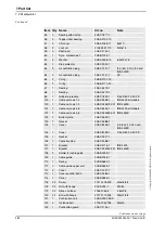
Page 322: ...ABB Robotics S 721 68 VÄSTERÅS SWEDEN Telephone 46 0 21 344000 Telefax 46 0 21 132592 3HAC 022032 001 Revision E en ...

Reviews: