background image

Section 4  Engineering

Creating Instances

3BSE040587R4401

59


Creating Instances

To create device instances that can be utilized for data presentation, do the 
following. 

1.

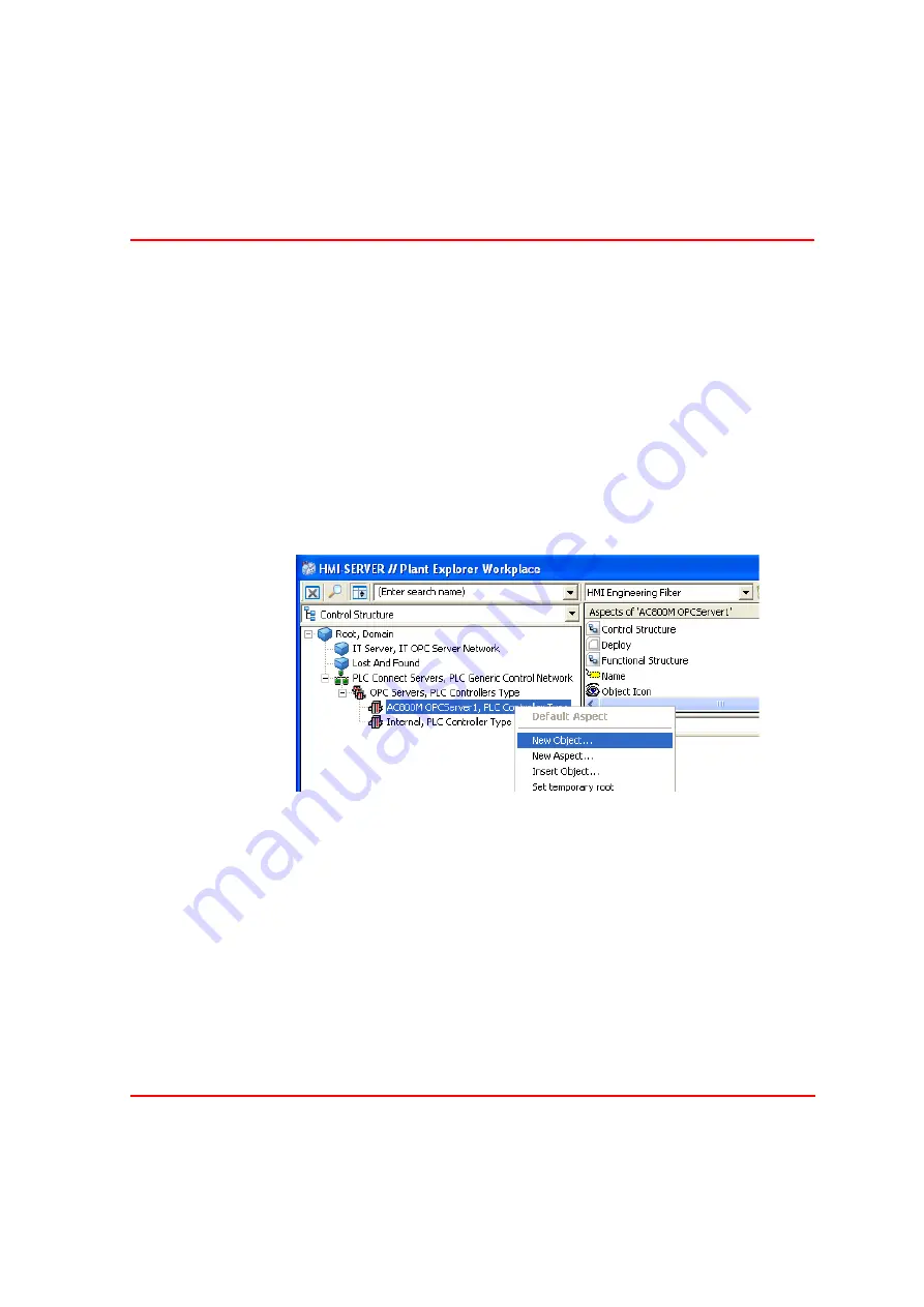
Open the Control Structure and select the OPC server for the PLC that contains 
the properties you want to access. 

2.

Right-click the OPC server and create a New Object. Select one of the object 
types created in the previous chapter e.g. “Simple OnOffMotor” and give it a 
name e.g. M1.

3.

The Control Structure should now have the following contents:

If you want to create several objects from one object do as follows. Choose Generic 
Control Network
 and then the aspect Generic Control Network Configuration. 
There you find one yellow cube with a star, and one yellow cube with a red cross. 
see 

Figure 26

. With these you can create or delete several objects.

Figure 25. Control Structure

Summary of Contents for IndustrialIT Compact HMI 800

Page 1: ...IndustrialIT Compact HMI 800 System Version 4 1 Getting Started ...

Page 2: ......

Page 3: ...IndustrialIT Compact HMI 800 System Version 4 1 Getting Started ...

Page 4: ...s document This document and parts thereof must not be reproduced or copied without written per mission from ABB and the contents thereof must not be imparted to a third party nor used for any unauthorized purpose The software or hardware described in this document is furnished under a license and may be used copied or disclosed only in accordance with the terms of such license This product meets ...

Page 5: ...ciples Aspect Objects 21 Aspects 21 Structures 23 The Operator Workplace and Plant Explorer Workplace 23 General User Interface 25 The Plant Explorer Workplace Window 25 Section 3 Installation General 27 Supported Standard PLCs 28 Compact HMI 800 Preconfigurations 31 Start Up 32 Connectivity to AC 800M 33 Installation and Configuration of OPC Servers for PLCs 34 Connection to Third Party Alarm Eve...

Page 6: ... 57 Adding Trend Display 58 Creating the Device Object Instances 58 Creating Instances 59 Connecting the Instances to Real Signals 61 Building the Functional Structure 64 Adding Process Displays 68 Adding Trends 71 Adding Alarm and Event list for a plant Area 77 Adding Navigation 77 Adding Shortcuts for Navigation 78 Shortcuts in the Application Bar 79 Shortcuts in the Display Bar 80 Messaging Con...

Page 7: ...n 96 Start Display 96 Display Links Aspect links 96 Shortcuts in the Display Bar 97 Shortcuts in the Application Bar 97 Context Menu 97 Hot Keys 97 Simple Scenario for Navigation 99 Faceplate Usage 100 Trend Usage 103 Accessing Trend Display 103 Trend Area 104 Tool Bar 104 Alarm and Event Usage 105 Process Alarms 105 Alarm Band 108 System Alarms 108 Process Events 109 System Events 110 Section 6 S...

Page 8: ...124 Start System 125 Autonomous Redundancy Setup 127 Change the Windows Computer Name in the Server Node 128 Change the Windows Computer Name in the Client Node 135 Connect and Disconnect Client Nodes 135 Disconnect a Client 136 Spare Part Computer 137 Defragmentation 138 Virus 138 Windows Update 138 Save of OPC IP Address for PLC Connect 138 Using Virus Protection with Compact HMI 800 139 Introdu...

Page 9: ...nnect 151 Visual Basic Controls 152 Graphic Primitives 152 Special Library 152 Subelements 153 Tank Library 153 Other Libraries 154 Library of PLC Subelements 154 The AlarmState Object 155 The WarningLevel Object 156 The AlarmWarning Combo Object 156 Configuration of PLC Connect Graphic Elements 157 Creating Graphic Element Aspects 157 Increasing Performance of a Graphic Element 158 Creating PLC C...

Page 10: ...ent 173 Inserting PLC Connect Graphic Elements in Graphic Displays 177 Library of PLC Process Icons 178 Three controls are used 180 ValveSimple 180 PgErrorIndicator 181 StatusBox 181 Linking Properties to Graphic Elements 183 Using Expression Builder to link a Property 183 Using the Linked Input Property 186 Creating New Graphical Libraries 187 INDEX 189 ...

Page 11: ...m the Start menu Start All Programs ABB Industrial IT Base System Documentation See Related Documentation on page 13 for a complete list of referred instructions Among these instructions there might be chapters describing functionality that is not a part of this product and hence obsolete Intended User This instruction is intended for several users Process operators with experience of process cont...

Page 12: ...ded process performance leading to personal injury or death Therefore comply fully with all Warning and Caution notices Applicable Specifications This product meets the requirements specified in EMC Directive 89 336 EEC and in Low Voltage Directive 72 23 EEC Electrical warning icon indicates the presence of a hazard which could result in electrical shock Warning icon indicates the presence of a ha...

Page 13: ...ion procedures System Administration and Security Contains instructions about how to administrate and set security in your System Software System Extended Operation Describes operation of the Operator Workplace System Operator Workplace Configuration Describes configuration of the Operator Workplace and Plant Explorer Engineering Graphics This instruction describes how to use Graphics IndustrialIT...

Page 14: ...ated to object management names security etc Aspect See Aspects on page 21 Aspect Objects See Aspect Objects on page 21 BDM Bulk Data Manager CEXbus Communication module expansion bus used in the AC 800M Controller CNCP Control Network Clock Synchronization Protocol COM Microsoft Common Object Model CS Connectivity Servers provide access to controllers and other data sources CTK Configuration Tool...

Page 15: ...ns intended for Production System FDA Food and Drug Administration FDT Field Device Tool It is an open standardized communication interface for integrating field devices and their application into control systems or device management tools e g Engineering Tools and Asset Management Tools FF FOUNDATION Fieldbus GSM Global System for Mobile communication HSE High Speed Ethernet FOUNDATION Fieldbus H...

Page 16: ... Control Aspect Plant Explorer An application that is used to create delete and organize Aspect Objects and Aspects in the Compact HMI 800 The plant explorer organizes the Aspect Objects in structures according to functionality location etc You can also use it to browse and search the structures of the plant PLC Programmable Logic Controller Controller for primarily discrete logic control PNSM PC ...

Page 17: ...1 17 SNTP Simple Network Time Protocol SOE Sequence of Events SQL Standard Query Language UTC Coordinated Universal Time VPN Virtual Private Network WMI Windows Management Instrumentation Table 2 Terms and Definitions Continued Term Description ...

Page 18: ...Terminology About This Book 18 3BSE040587R4401 ...

Page 19: ... IndustrialIT Compact HMI 800 is designed to be an HMI to any kind of automation solution It interfaces to AC 800M and most other PLCs found on the market It is based on the IndustrialIT Base standard system To make it easy to set up and install the product some configurations are pre set at delivery Figure 1 System Overview ...

Page 20: ...System Overview Section 1 Compact HMI 800 Overview 20 3BSE040587R4401 ...

Page 21: ...ect node object workplace object etc Aspects There are a number of different types of information connected to each object These types of information are called Aspects in the Aspect Object solution For example a valve may have a mechanical drawing a faceplate for control purposes a graphical representation in a graphical display and so on Aspect Objects have a number of default aspects for exampl...

Page 22: ...ether Figure 2 shows how the concepts fit together The physical valve is modeled and represented in a graphical display This valve that is now an Aspect Object has a number of Aspects of which four are presented here Each aspect has at least one view Figure 2 Aspects with Aspect Views ...

Page 23: ...e and Functional Structure The Operator Workplace and Plant Explorer Workplace The Operator Workplace The Operator Workplace is the environment from which the operator views and controls the process in the plant By logging in as an Operator the Operator Workplace will be started After logging in the start screen is displayed It is usually configured by the Application Engineer and intended as a st...

Page 24: ...nd the bottom of the Operator Workplace there are tool bars to control the system and the process These areas contain important information and are never covered by displays The tools in these toolbars represented by Icons are used to interact with the process and the Compact HMI 800 Figure 3 The Operator Workplace Window ...

Page 25: ...eers who wants to configure an Operator Workplace General User Interface Compact HMI 800 workplaces use the window system provided by Microsoft Windows They are designed so as to retain a familiar environment Plant Explorer works in a similar way as Windows Explorer regarding for example the following functions cut paste copy shortcut tools drag and drop operations within and between the Workplace...

Page 26: ... Explorer Workplace Section 2 Terms and Common Principles 26 3BSE040587R4401 Read more about the Plant Explorer in the IndustrialIT Base System Operator Workplace Configuration instruction Figure 4 The Plant Explorer Workplace Window ...

Page 27: ...kplace client with one power cord one keyboard one mouse one dongle one cable for dual VGA four Dell and two Microsoft backup DVDs one Symantec Norton Ghost box one product box Including Getting Started manual one mouse pad one Server Restore DVD and one As Manufactured DVD one box including VB Visual Basic 6 for Process Graphics and Aspect Express 0 4 client PCs For operator workplaces optionally...

Page 28: ...es that are compliant to the communication standards OPC Modbus RTU Modbus TCP SattBus and Comli The Compact HMI 800 supports connections to PLCs both via OPC with specific communication hardware as well as via serial communication channels Besides the serial channels there is no upper limit on how many PLCs that may be attached to the system Instead the total number of communicating signals that ...

Page 29: ...ion Supported Standard PLCs 3BSE040587R4401 29 Figure 5 Rear side PC connections Power Cord Control Network Keyboard USB Communication Serial communication VGA connections Redundant Control Network e g AC 800M com Dongle ...

Page 30: ... to be started automatically Each PC is equipped with a dual network card at delivery If the intention is to connect any of the PCs with an intranet etc a separate network for client servers and PLCs should be considered It is also possible to split the client server and control networks for performance and other reasons In any case configure the addresses according to the IndustrialIT Base System...

Page 31: ...onfigured to help ease of use These are described in this chapter Compact HMI 800 system is limited to one server and up to 4 clients In total this adds up to 5 Operator Workplaces one on each client and one on the server The server is also used as an Engineering Workplace Figure 7 Separate Network Setup Server client 1 PLC s Switch 2 Optional clients Switch 1 ...

Page 32: ... be used in special system administration tasks Default passwords for the Compact HMI 800 users are the same as their user names Start Up After installing the hardware the system is started as follows Power up network switches and other communication equipment Power up the server node Power up the clients Power up PLCs and other equipment When the nodes have started a welcome screen asks the user ...

Page 33: ...ect to all PLCs and Controllers PLC Connect can be used to connect AC 800M C controllers versions 3 0 3 2 using the corresponding Control IT OPC Server 3 0 3 2 PLC Connect can also be used to directly connect AC 800M 2 0 2 1 2 2 3 0 3 1 3 2 and AC800C 2 2 3 2 versions using any of the following protocols with PLC Connect acting as master and AC 800M C as slave Serial connection and the Comli proto...

Page 34: ...the Figure 8 Installation and Configuration of OPC Servers for PLCs Compact HMI 800 can interface to standard PLCs The connection is done using a specific communication driver or via an OPC server for the PLC To connect one or more PLCs via an OPC server follow the description below Install the OPC server for the PLC The OPC server shall be installed as a Windows service if possible Below is a typ...

Page 35: ...the Compact HMI 800 server fill in the server node name 10 Select the OPC server in the OPC server drop down list 11 Press OK and then the Create button Now the OPC server is installed Connection to Third Party Alarm Event OPC Server To get time tagged alarms from the controller into the Compact HMI 800 alarm list the OPC AE client function of Compact HMI 800 should be used To associate an alarm w...

Page 36: ...ompact HMI 800 node Create a Service Group for the Event Collector Create a Service Provider for the created Service Group Figure 9 AE OPC Service Group Do the configuration of the Service Provider and of the AE OPC Server Select the current PLC_C node in the Service Provider Definition Aspect and select the Prog_ID for the current OPC A E Server in the Service Group Definition Aspect ...

Page 37: ...3 Installation Connection to Third Party Alarm Event OPC Server 3BSE040587R4401 37 Figure 10 Service Provider Definition Figure 11 Service Group Definition In the Controller PLC you need to configure the alarms ...

Page 38: ... done with the Compact Control Builder for AC 800M PLC Control Builder The AC 800M Connect can not be used in the 800xA System if the OPC Server for AC 800M is to be used for alarm handling as described here This limitation is only valid to the OPC Server for AC 800M and not for third party OPC Servers In this example three alarms are defined and used so they will be displayed on one Object in the...

Page 39: ...e Add the Aspect Name aspect and use the copy function from the Aspect Control Tab in the Object Type Definition Aspect This has been done for the TestType as displayed below Figure 13 Aspect Control Tab in the Object Type Definition Aspect The following Aspects are also added to the Object Type as usual Alarm List Alarm Status and a Faceplate In this example this Graphic Element was also created ...

Page 40: ...he Object is configured with the SourceName from the AE OPC Configuration Figure 15 Control Structure and the Aspect Name aspect When the alarms are activated the following information will be displayed in the Alarm List Figure 16 Alarms in the Alarm List The Faceplate and the Graphic Element is displaying the Summary Alarm State of the Object ...

Page 41: ...nication please note the following Make sure that you use the same network mask in the AC 500 as in the Compact HMI 800 i e 255 255 252 0 If you are using the AC 500 OPC Server please note the following The OPC servers should be set in dcom config to always be running as the same user as the user running the AC 500 control builder This is done by logging in as SysAdmin and then follow the followin...

Page 42: ...C Server Section 3 Installation 42 3BSE040587R4401 Figure 18 DCOM Config in Component Services 4 Right click the icon and select Properties then select the Identity tab to get the dialog below Figure 19 OPC Server for CoDeSys V2 0 Properties ...

Page 43: ... be used for both configuration and operation with the AC 500 controller OPC Server for AC 800M is Preinstalled If you are using AC 800M controllers the Compact HMI 800 is ready to connect to the AC 800M controller out of the box The OPC server is installed and the Compact HMI 800 has been configured accordingly How to connect AC 800M see Figure 20 Figure 20 AC 800M connections Power Cord Control ...

Page 44: ...P addresses Below the IP addresses for the different network nodes are presented The system is interconnected using Work Groups with the nodes defined in a Host table This means that a standalone system does not need a Domain Server or a DNS server If the installation shall be included in an existing domain please refer to the IndustrialIT Base System Automation System Network instruction Section ...

Page 45: ...ore information Workplace client 1 172 16 4 71 Workplace client 2 172 16 4 72 Workplace client 3 172 16 4 73 Workplace client 4 172 16 4 74 AC 800M CB PLC 172 16 4 151 172 16 4 255 3 d party PLCs 172 16 6 0 172 16 6 150 Switches 172 16 5 245 172 16 5 255 Use the IP address mask 255 255 252 0 for all nodes Table 5 Nodes and IP Addresses Continued Node IP Address ...

Page 46: ...IP Addresses and Workgroups Section 3 Installation 46 3BSE040587R4401 ...

Page 47: ...Industrial IT PLC AC 800M Compact Control Builder and look under Help Manuals Engineering Workflow Compact HMI 800 provides a variety of tools for acquisition of data and presentation of data on a computer screen Below there are a simple workflow with recommended steps to engineer the Compact HMI 800 Decisions must be made on how to organize the displays write control applications and how to secti...

Page 48: ...I 800 The signal objects are grouped to form an object representing a controlled device or process object To reduce the effort involved in this the Compact HMI 800 includes the possibility to use Object Types Object Types are the base for the object instances Objects instances are representations of each individual real device in the factory 3 Creating the device objects and related signals The si...

Page 49: ...d to define objects that represents the different types of devices and process objects for which data will be fetched in the PLCs Object types hold information and functionality of a specific type of object e g a pump In this chapters the object type and its properties are defined The following steps will be described Creating an object type Adding signals to an object type Adding graphical Elemen...

Page 50: ...rolled by the PLC there should be an object type created To create an object type open the Plant Explorer by double clicking on the My ePlant icon on the desktop Then change to Object Type Structure in the drop down menu in the upper left side of the window and go to the PLC object as shown below To create an object type representing a specific type of device right click the PLC object and select ...

Page 51: ...n Object Type Signal objects are used to read and write data from to the PLCs For each device type we need to define which properties we need to read or write from to the PLC for this type of device This is done by creating a PLC signal for each of the properties that should be accessed To configure e g Simple OnOffMotor do as follows 1 In the Object Type Structure expand the Simple OnOffMotor dow...

Page 52: ...tinue with the next chapter Adding Graphical Elements To be able to present data from instances of the object type in graphical displays a display element must be created This is done by following the steps below See also Section 8 PLC Connect Graphic Elements 1 Open the Object Type Structure 2 Select the Device object type created earlier Right click and select New Aspect from the context menu th...

Page 53: ...change in the List of properties show in the Object Property tab in the Expression builder 3 Click on e g Motor_ON 4 Then scroll down and double click Value Binary PCA in the right column now the property has been selected 5 Write a comma in the fill color field 6 Select the color tab below 7 Now select the color representing on Double click on the color named measure 8 Write a comma in the fill c...

Page 54: ...Adding Graphical Elements Section 4 Engineering 54 3BSE040587R4401 Figure 24 An Example of a Display Element Configuration ...

Page 55: ...ste the copied Faceplate standard 3 Open the Config View for the faceplate aspect by using the context menu right click on the aspect 4 Select the Buttons tab 5 Double click the Object column in the row with a 1 Icon and browse to the newly created Motor_Start signal 6 Click on the Property Name column and select the value property Resize the window if the screen does not show up properly 7 Select...

Page 56: ...vent Configuration aspect on the signal objects are used to create events and alarms based on the properties received from the PLC The events and alarms are viewed and accessed by the operator using alarm and event lists A top level alarm list which is handling all alarms in the installation is preconfigured It is possible to configure other alarm lists on lower levels for example for a section of...

Page 57: ...n alarm for a specific area select the alarm list aspect for that area Adding History Logging The Log Configuration aspect is used to make an historic log of a value received from the PLC The log can be defined either on the signal instances or on the signal types To define a log on a type and by this for all instances go to the Object Type Structure and add a Log Configuration aspect to the Signa...

Page 58: ...onal fields if needed 8 The trend is now configured and will show up on each instance of this type Creating the Device Object Instances Data from the PLCs are received by signal objects defined in the control structure The signals are grouped below device objects representing devices in the factory To be able to present the data in displays in Compact HMI 800 the device objects are equipped with g...

Page 59: ...te a New Object Select one of the object types created in the previous chapter e g Simple OnOffMotor and give it a name e g M1 3 The Control Structure should now have the following contents If you want to create several objects from one object do as follows Choose Generic Control Network and then the aspect Generic Control Network Configuration There you find one yellow cube with a star and one ye...

Page 60: ...ances Section 4 Engineering 60 3BSE040587R4401 If you click on the yellow cube with the star you will get the following dialog box See Figure 27 Figure 26 Yellow Cubes for Object Creation Figure 27 Create New Object ...

Page 61: ...ll get numbers in row after the name Connecting the Instances to Real Signals Now each signal has to be connected with the corresponding property in the PLC Do this by opening the signal configuration aspect To connect the signals check the connected radio button in the variable connection field Click Browse to connect to the property in the PLC See the Figure 28 below After selecting the property...

Page 62: ...o be connected by just adding the address string for the property To test your connection select the PLC Connect Server objects and the Deploy aspect Click the Deploy button Note that the Browse function is only available if the OPC server implements the browse interface Figure 29 OPC Browser Window ...

Page 63: ...data is retrieved from the PLC Another way of getting live data is to choose the aspect named Object Dialog see Figure 32 Then you will get live data from all signals that are placed in this object You will also get an icon with alarm indication and you can also see if a signal is forced or not If you get signal values here you know that PLC Connect is working correctly Figure 30 Deploy Figure 31 ...

Page 64: ...To perform this objects should be placed in the Functional Structure to reflect the functions in the plant Then Objects in the Control Structure should then be inserted into the Functional Structure Building objects are described in IndustrialIT Base System Operator Workplace Configuration instruction To create the objects in your Functional Structure follow the steps below 1 Go to the Functional ...

Page 65: ...re to the functional structure and for this we use the Bulk Data Manager BDM tool 4 Switch structure to the Control Structure 5 Select the root object in the Control Structure and open the Bulk Data Manager place object in Functional Structure aspect 6 Right click the aspect and select Edit and Check Out 7 If this is the first time you use the Bulk Data Manager BDM please select the menu item Bulk...

Page 66: ...in the Control Structure and drop them in the Bulk Data Manager See Figure 34 below 9 Move contents of Column F to column E select all texts in the column and cut it and paste it in column E Deselect the items in Column E and click the Save all objects button Figure 34 The Bulk Data Manager Figure 35 Move from the F column to the E column ...

Page 67: ... have now been placed also in the Functional Structure 11 You can now exit Excel select Not to save the changes Now you can see the results in top of the Functional Structure The objects are now ready to be dragged to the preferred places in the Functional Structure Figure 36 Copied Objects ...

Page 68: ...onal Structure to support the displays this was done in the previous chapter First add a structural object to host the graphics display as a graphics aspect if you did not go through the previous chapter 1 Select Functional Structure and the Root object 2 Open the context menu and select New object 3 Select a suitable object type depending on your application 4 Name it for example E g MU1 5 Click ...

Page 69: ...n 4 Engineering Adding Process Displays 3BSE040587R4401 69 8 Click the Edit button and start to edit the Graphics 9 To add a device to the graphic click Browse in the element browser Figure 38 Element Browser ...

Page 70: ...ments named Symbol Factory these are made available in the graphics builder by selecting the Symbol factory tab in the left toolbar and then right clicking the area and select components 14 Now Scroll down to the entry Symbol Factory Controls check the check box and click Apply then close the window with Close 15 These components can Now be used by clicking on the pump symbol and then placing it i...

Page 71: ...w to create a Trend Display aspect 1 A Trend Display can be created in any structure One proper structure is the Functional Structure 2 Select the place where you want to locate the Trend Display and select New Aspect in the context menu Figure 39 Select Structure Figure 40 Create New Aspect ...

Page 72: ...utton 5 Select the created aspect in the aspect list Note that there exist several different aspect categories of Trend Displays the Operator Trend the Trend Display and the Object Trend The differences between the three categories of Trend Displays are the user roles required to modify them Operator and Object trend can be accessed by Show All in the new aspect dialog Figure 41 Create Trend Displ...

Page 73: ...nds 3BSE040587R4401 73 6 The created Trend Display aspect will look like the figure below 7 The created Trend Display uses the default Trend Template you must select it in the Config View Figure 43 Trend Display Figure 44 Config View ...

Page 74: ...late from the Trend Template drop down list 9 Return to the Trend Display Main View 10 To insert an object make one of the following actions Click in the Object column and write the object name Or enter a dot Select a signal from the Select Object pop up dialog Figure 45 Select another Trend Template ...

Page 75: ...Section 4 Engineering Adding Trends 3BSE040587R4401 75 Drag the object and drop it in the Object Name column Figure 46 Select Object Pop Up Dialog ...

Page 76: ...ce Configuration instruction Figure 47 Select Trend Display Log If you are not selecting an aspect in the Aspect Name column see Figure 47 all properties for the selected object will be listed Press SHIFT while selecting property in the Property selection column see Figure 47 then only logged properties will be displayed If you are not selecting a Log Name SEAMLESS will be selected by default see ...

Page 77: ...n functionality between displays there are several methods available Below the four most common ways to navigate are listed Shortcuts make it easy to navigate to the most important and or most frequently used aspects of different aspect objects You can find different shortcuts in the Application Bar By clicking the Aspect Menu icon in the Tool Bar the Aspect Menu will be presented From the Aspect ...

Page 78: ...that by adding a shortcut to the RC1 Robot Cell object we can use the shortcut from all views of the cell e g if we add a shortcut to RC1 that points to RC2 we will be able to navigate to RC2 aspects from RC1 Graphical Display RC1 Trends Display RC1 Mechanical Drawing etc The figure below shows how the navigation works By adding a shortcut to the RC1 object pointing to the RC2 Graphic Display the ...

Page 79: ... Application Bar follow the steps below 1 Log on as SysAdmin 2 Add an Application Bar Shortcut aspect to the workplace object by doing like this a Right click on the workplace object and select New Aspect b Select Application Bar Shortcuts in the dialog and click Apply 3 Double click on the aspect and a dialog box opens See Figure 49 Figure 48 Application Bar Shortcuts Figure 49 Dialog Box for edi...

Page 80: ...ess to any viewable aspect associated with a particular object and its descendents The difference between a shortcut in the Application Bar and a shortcut in a Display Bar is that the shortcuts in the Application Bar are associated with the Workplace and are available at all times no matter which Display you have selected Shortcuts in a Display Bar are visible only when you have selected the Displ...

Page 81: ...ects should be linked 3 Double click on the aspect and a dialog box opens 4 Click on the Add button and a new dialog box pops up 5 Select structure object and aspect in the dialog box See Figure 51 6 Click OK and the shortcut will be added to the shortcut list 7 A Display Shortcut will be displayed in the Display Bar to the right of the other tools See Figure 52 Figure 51 Add Edit Display Shortcut...

Page 82: ...enger function to send alarm and events using SMS messages please go through the steps described below For detailed configuration information use the help button in the corresponding aspects Please note that you need to be logged on as SysAdmin to continue Please use the shortcut buttons shown to the right directly above this view to get quick access to aspects referenced below 1 Connect the Phone...

Page 83: ... that you are using including country code 9 Enter the Initialization string for the Phone you are using look in help for initialization strings For newer models of SonyEricsson phones use the Initialization command string AT CBST 0 0 1 CHSN 4 2 0 12 omit the characters 10 Configure the User that is supposed to receive the messages This is done in the Message Subscriber and Message Schedule aspect...

Page 84: ...cture To disable the Audit Trail function follow the steps below 1 Log on as SysAdmin 2 Open the Admin Structure in the Plant Explorer expand Administrative Objects and browse to aspect Domains HMI Server Audit Trail Config 3 Double click on the Audit Trail Config aspect to open the configuration view 4 Unmark the Audit Trail active check box and click Apply 5 The Audit Trail function has now been...

Page 85: ...roups of operators have different access rights to application areas This can be achieved by adding Security Definition aspects with structure range on top of the areas in the Functional Structure Individual objects can also have extended protection by adding a Security Definition aspect with object range directly on the object For more information how to configure security see the IndustrialIT Ba...

Page 86: ...w PLC Controller type should be followed for each controller When all controllers have been created and configured continue with the steps below 1 Copy the file to the Compact HMI 800 hard disc 2 Double click the file to start the Import Export tool 3 Select the Object Type structure in the structure selector box in the Import Export tool 4 Right click the PLC Object Types Object and select import...

Page 87: ...ins these objects in the Compact HMI 800 structures 13 Press OK for each imported item 14 Repeat steps 7 13 for each PLC Controller 15 Before the objects will start communicating a deploy has to be done This conclude the transfer of the PLC Process Objects and Corresponding signal objects from the 800xA to the Compact HMI 800 ...

Page 88: ...Import to Compact HMI 800 Section 4 Engineering 88 3BSE040587R4401 ...

Page 89: ...the time regardless of what displays are shown One example is the alarm line Tools in the application bar influence the system or handles aspect objects Some of the tools are very useful for navigating Display bar It influences the display area only and is the main area for navigation between displays It changes when the base display is changed Display area It is used to present the different type...

Page 90: ... used to show information that should be visible all the time The main use is to show the latest alarms give easy access to the alarm situation for a process area and direct links to displays or other aspects and tools Below is a description of the available tools Figure 53 Operator Workplace in Operator Mode Figure 54 The Application Bar Application bar Display bar Display area ...

Page 91: ... alarm presented at the moment To go to an alarm list click on the button Alarm Line The Alarm Line is an Alarm List specially configured to show the three latest process alarms Figure 55 shows an example of an Alarm Line Clock Shows the system clock ABB logo Can be configured Below the alarm oriented information described above the following tools are available Process Alarm Click on the Process ...

Page 92: ...e tool has two states up and down When the button is down the Object Browser is displayed in a separate window When the button is up the Object Browser is closed Aspect Menu Favorites Use the Aspect Menu tool to group and organize the most visited aspects for fast navigation Click on the icon and the Aspect Menu will be presented at the configured position on the screen Print screen Print Screen i...

Page 93: ...cently viewed aspects or type of information the latest used displayed on top By dragging an aspect to the Drop Target it will be displayed in the Display Area The Pinned Tool pins the display like a note on a billboard The display can not be changed by clicking on the Backward or Forward button or drop a display on the Drop Target tool To enable change of display you first have to remove the pinn...

Page 94: ... display in this selected display area by using one of the ways listed above Display Area This is the main area for the displays see Figure 57 below It is used to show a view of an aspect a display and can be used to present information like process displays trend displays alarm lists etc Displays can appear as base displays covering the entire Display area or as one or more overlap displays The t...

Page 95: ...lace in the Compact HMI 800 contains a default set of tools to navigate among structures aspects and objects This section includes recommendations of how to use these tools to navigate through displays The recommended tools and methods are adequate for most applications At delivery the Compact HMI 800 is configured not to include this area It is possible make it visible by configuration and revert...

Page 96: ... Tools on page 89 and in IndustrialIT Base System Operator Workplace Configuration Start Display At log in as an Operator the start display will be presented on the screen It is recommended to program one of the functional keys F1 F12 or the HOME key to bring up this display Display Links Aspect links In a Process graphics display links to other displays may be defined These display links are conf...

Page 97: ...right of the standard tools in the application bar Application bar shortcuts remains as you switch displays and no inheritance occurs Shortcuts in the application bar is an alternative or a complement to Hot Keys In the Application bar there are a number of shortcuts by default Context Menu By right clicking an object in a display or alarm list etc a list of aspects associated to the object is pre...

Page 98: ...played in the Object Shortcuts tool Selection is set for example when clicking a Graphic Element in the object browser An object is highlighted when placing the mouse pointer over a graphic element Table 6 Workplace Hot Keys Hot Key Operation ALT HOME Show Cursor CTRL F Find tool CTRL SHIFT 3 All process alarms CTRL SHIFT 4 All process events CTRL SHIFT 5 System alarms CTRL SHIFT 6 System events C...

Page 99: ...io below shows some examples of navigation the scenario is not available in the product in Compact HMI 800 Display 1 Overview containing 3 tanks each representing a section of the plant Table 7 Selected Object Hot Keys Hot Key Operation CTRL G Show Object Type Figure 59 Navigation Scenario Display 1 Display 2 Display 3 ...

Page 100: ...Display 1 the Display Link is referring to Display 2 3 To go to Display 3 alternatively a Press F7 functional key F7 configured as a key shortcut b Left click on the Display Link in Display 2 4 To go back to Display 1 alternatively a Press F5 functional key F5 configured as a key shortcut b Click on previous Display in the Display tool bar c Use the Display history tool in the display bar Faceplat...

Page 101: ...plate and contains more information and normal operator commands Extended View This view usually has two groups of tabs with additional process information and functionality This view is used to display the maximum amount of information and is intended for the process engineer or the advanced operator The active Faceplate view is indicated at the bottom of the Faceplates the corresponding view sel...

Page 102: ...Faceplate Usage Section 5 Operation 102 3BSE040587R4401 The different views are presented in the figures below Figure 61 Reduced Faceplate and Faceplate View Figure 62 Extended Faceplate ...

Page 103: ... property It is possible to insert new traces for comparison with the existing in all trends but the modified trend can only be saved if it is an Operator Trend Functions for rulers time zooming magnifying glass etc are available in the Trend Display The time offset function can be used to trace a signal in real time and compare it with values from yesterday It is possible to present trend relatio...

Page 104: ...he case when you use zooming together with the ruler To change color of Background Table Trace area Grid Axis or traces the Trend Template must be changed Tool Bar The Tool Bar contains buttons for frequently used functions to operate the Trend Display The Tool Bar lets you among other things freeze the graphical view in time select a point on the graphical view and then read the corresponding tim...

Page 105: ... An event list includes the history for both alarms and events Alarms or events can have different priorities that are indicated by different colors in e g lists Process alarm and event lists can either include all process alarms or alarms for a specific part of the process down to a single process object The following pre configured lists exist to view different types of alarms and events Process...

Page 106: ...faceplate to see a list of alarms for a specific object see Figure 65 Click on an Alarm Band button to see a list of all alarms Figure 65 for a specific process area see Figure 64 For more information about Alarm Band see Alarm Band on page 108 From an Alarm Line in the Application Bar using the context menu see Figure 64 Figure 64 Accessing the Process Alarm List Alarm Band Button Alarm Line Alar...

Page 107: ...wledge alarms for an object in the following ways By clicking on the Ack State box for the alarm in the list By right clicking on an alarm line and selecting Acknowledge all alarms for that object will be acknowledged or Acknowledge Selected only the selected object will be acknowledged from the context menu By selecting one or several alarms in the alarm list and clicking the Acknowledge button g...

Page 108: ...looks like in the figure above Figure 66 the alarm band has lost contact with some server partial connected In this case it is still possible to for example make acknowledge System Alarms System Alarms are alarms generated from the Compact HMI 800 System such as network problems file system errors or server errors In many cases these alarms need to be taken care of by your system administrator The...

Page 109: ...r Figure 67 Process Events There are several ways to access a Process Event List for an object The following are some typical examples that may be configured from an Event Line in the Application Bar using the context menu Figure 67 Accessing the System Alarm List Figure 68 System Alarm List System Alarm Band ...

Page 110: ... the Tool Bar System Events There are several ways to access a System Event List for an object The following are some typical examples that may be configured from an Event Line in the Application Bar using the context menu from the System Event List button in the Tool Bar Figure 69 Process Event List ...

Page 111: ...Section 5 Operation Alarm and Event Usage 3BSE040587R4401 111 Figure 70 System Event List ...

Page 112: ...Alarm and Event Usage Section 5 Operation 112 3BSE040587R4401 ...

Page 113: ...ter On the server machine users Operator AppEng and SysAdmin are visible on the Windows Welcome screen Operator behaves in the same manner as on the client as the server machine acts as a client as well AppEng is allowed to see the following structures in the Plant Explorer Functional Control User Object Type Default filter for the AppEng is PLC Engineering Filter The PLC Engineering Filter includ...

Page 114: ...troller for this server is configured in the Plant Explorer Alarm and event services are connected to the controller See Connectivity to AC 800M on page 33 License server software is installed on the server machine License clients are installed on the client machines License server is loaded with a license file which provides correct functionality of the system The client machines use the server m...

Page 115: ...Users on page 33 To add a new user to the Compact HMI 800 after it has been created in Windows follow the steps below 1 Log in as System Administrator 2 Start the Configuration Wizard 3 Go to System Administration System Users 4 Click Add Windows Account button 5 Add a user 6 Click Next and Finish To add a user to a new group do as follows 1 Log in as System Administrator 2 Start the Configuration...

Page 116: ...lder with Compact HMI Native Language Support files named CHMI_NLS A copy of the contents of the DVD is also available on the Backup Disk D The Server Restore DVD Ghost image is used in case of a system crash This is an image of the C disk before the system is created This image is to be used on recovery because the restore functionality demands that no system exist on the computer Backups are con...

Page 117: ...leting the system manually by just removing the files from the hard drive is not enough To use the supplied Ghost software and to restore a Ghost image a bootable Ghost CD is required Use one of the supplied Bootable Ghost CDs Backup and Restore of Configuration Data To backup the configuration data of the system follow the steps below Note that the data for the applications that are not integrate...

Page 118: ... the following steps 1 Open the Configuration Wizard and select Restore System and click Next 2 If the backup shows up in the window go to step 22 If the backup does not show up in the window click Select Path and add and then browse to the folder shown below 3 Click OK and OK again 4 Select the backup that was done in step 2 and press Next If the change of Computer Name has been done before the s...

Page 119: ...Restore of Configuration Data 3BSE040587R4401 119 5 Now select Generate New System ID and enter the system name e g HMI Server55 System and press Next 6 Press Next in the dialog below and then Finish Figure 73 System Directories Selection ...

Page 120: ...the automatic system backup the data can be stored in the File Viewer Aspects To do this follow the steps below 1 Create a zip file containing all files included in the controller application 2 Log on as user AppEng and open Plant Explorer 3 Select an object that represents the part of the plant that the control application covers e g a plant section object in the functional structure 4 Right clic...

Page 121: ...e and Standard Tools 4 Move on through the installation by pressing Next until the User Information dialog box is shown 5 In the User Information dialog box write the information including a working e mail address and eventual Serial Number Without a serial number the software will only function for a limited period of time 6 Click Next to install the software to its default path Select Change if ...

Page 122: ...eps below to upgrade the Compact HMI 800 to a new version 1 Backup the configuration data in all nodes For the Compact HMI 800 configuration data use the system backup function to make a backup as described in Backup and Restore on page 116 2 Make a safety Ghost copy of the C disk of the server computer using the Norton Ghost software supplied in the original delivery of the Compact HMI 800 3 Boot...

Page 123: ...hown in the computer under Add Remove Programs in the Control Panel the versions can be verified If there is a newer version listed than what is installed this software should be downloaded and installed in each node where there is an older version of the software installed This is done in the following way 1 Stop the Compact HMI 800 system services on the server described in To Stop and Start the...

Page 124: ... the power follow these steps 1 Log in as SysAdmin 2 Open the Configuration Wizard START All Programs ABB Industrial IT Base System Configuration Wizard 3 In the dialog above select System Administration 4 Then click Next and Next again 5 In the window below select Systems and press Next Figure 75 Select Type of Configuration ...

Page 125: ...t until the system has stopped the dialog in step 2 shows up Start System To start the system without switching off and on the power follow these steps 1 Log in as SysAdmin 2 Open the Configuration Wizard START All Programs ABB Industrial IT Base System Configuration Wizard Figure 76 Select Type of Configuration HMI Server88 ...

Page 126: ...ystem Section 7 Administration 126 3BSE040587R4401 3 In the dialog above select System Administration 4 Then click Next and Next again 5 In the window below select Systems and press Next Figure 77 Select Type of Configuration ...

Page 127: ...HMI systems are running in parallel accessing the same controllers One of the systems are considered to be the main system and the second is the backup system All configuration changes should be done in the main system and then transferred to the backup system by using the system backup function The setup of an autonomous redundancy configuration is done by the following main steps 1 Make a system...

Page 128: ...Computer Name in the Server Node To change the Windows Computer Name of the Compact HMI 800 Server node please go through the following steps 1 If the node name is change directly after delivery the steps 2 and 3 can be omitted In this case proceed to step 4 2 Make a Ghost backup of the node using the Norton Ghost software supplied in the original delivery of the Compact HMI 800 3 Make a system ba...

Page 129: ...Next and Next again 8 Select System Start Stop or Delete and press Next 9 Select Delete System on a Node and click Next 10 Be aware of that all configuration data will be lost if you proceed and has not done step 1 and 2 11 Click Next and Finish 12 Now wait until the system has been deleted the dialog in step 6 shows up with some fewer options then Exit the Configuration Wizard 13 Restart the Comp...

Page 130: ...ialog below 17 Enter the new name e g HMI Server55 and press Apply and exit the License Status Viewer 18 Restart the computer and log in as SysAdmin 19 If you are using the AC 800M OPC server open the OPC server configuration dialog and disconnect and connect each of the controllers once After this save the configuration 20 If you are setting up an autonomous redundant backup system otherwise skip...

Page 131: ... again 24 Select the backup that was done in Step 2 or that was copied from the main system if you are setting up an autonomous redundant backup system and click Next If the change of Computer Name is done before the system has been configured use the restore dump available on the DVD supplied in the Compact HMI 800 delivery another path needs to be added 25 Now select Generate New System ID and e...

Page 132: ... the Windows Computer Name in the Server Node Section 7 Administration 132 3BSE040587R4401 26 Press Next in the dialog below and then Finish Figure 82 System Directories Selection Figure 83 Node Configuration ...

Page 133: ...ystems references to the OPC servers should be reconfigured to make sure that the correct OPC servers are used To do this follow steps a e below for each OPC server a Open Plant Explorer and go to the Control Structure b Click on each of the objects of the type PLC Controller Type and select the PLC controller configuration aspect as shown in the figure below Figure 84 OPC reconfiguration ...

Page 134: ...LC Connect Servers and the Deploy aspect 30 Click Deploy 31 When deploy has ended the Node name change for the server is completed 32 If clients are connected to the server each client needs to be updated as described in the following four steps 33 Log in as SysAdmin in the Client 34 Open the Hosts file using Notepad and update the file with the new name of the server 35 Restart the client 36 Conn...

Page 135: ...rivers etc hosts 5 Remember that if the name of the server has been changed the License Status Viewer should be opened and the CLS machine be changed 6 Connect the client to the server as described in chapter Connect and Disconnect Client Nodes on page 135 7 The node name change of the client is now ready Connect and Disconnect Client Nodes Client nodes has to be connected to the system This is do...

Page 136: ...Next and then Finish 9 The client has now been added Disconnect a Client To Disconnect a client from a system go through step 1 5 above and then continue with these steps 1 Select Remove Client and click Next 2 In the dialog below select the client to be removed Figure 86 Add a Client Node ...

Page 137: ... The spare part computer can be used as both client and server computer Spare Part Computer used as Server When using the computer as a server the license file and related dongle has to be moved from the original server to the spare part computer In addition the latest backup file needs to be restored before the server is ready to be used To restore the server please follow the instructions in cha...

Page 138: ...s helps keeping the good performance of your computer and the stability of your software This must be done in a secure manner as recommended below The system administrator or a central engineering department can make the updates available on a dedicated distribution server on the office or corporate network by installing them from CD DVD or by downloading them from a trusted server e g on the Inte...

Page 139: ... frequent run virus scans Virus checking affects the performance and response times of any computer system For an automation system such as Compact HMI 800 where real time performance and reaction times must not be compromised the impact of virus checking must be limited This can be accomplished by excluding certain frequently accessed directories and file types from on access scanning and by runn...

Page 140: ... scanned on demand at regular intervals However since this scanning will impact system performance and reaction times it should be done when normal system activity is low On access scanning for Low and high risk processes McAfee allows you to select different on access scanning options for low and high risk processes see Figure 88 This feature shall be enabled during testing Figure 88 Enabling dif...

Page 141: ...fault processes See Figure 89 When pressing Additions the default file types defined in the current McAfee DAT file are listed Here the additional file type afw was added When pressing Exclusions a list of the disks files and folders that are excluded from on access scanning is presented Figure 90 Figure 89 Settings for default processes ...

Page 142: ...vant folders as shown in Figure 91 The folders and file types that need to be excluded depend on which products are installed A list is provided in Folders Excluded from On access Scanning on page 148 Note that Also exclude subfolders On read and On write were checked Figure 90 List of disks files and folders excluded from on access scanning ...

Page 143: ...tings 3BSE040587R4401 143 Settings for low risk processes The Compact HMI 800 system function Afwworkplaceapplication was added to the list of low risk processes as shown in Figure 92 Figure 91 Adding a folder to exclude from on access scanning ...

Page 144: ...rocesses see Figure 89 The same folder and file type exclusion settings that were used for the default processes see chapter Folders Excluded from On access Scanning on page 148 were used also for low risk processes In addition the following folder was also excluded Program Files ABB Industrial IT Operate IT Process Portal A bin Figure 92 Adding low risk processes ...

Page 145: ...ated Since scanning these folders will impact system performance and reaction times it should be done when normal system activity is low For the purpose of the test cyclic scanning was configured for all folders excluded from on access scanning This is illustrated in Figure 93 note that Figure 93 does not show all relevant folders The schedule is specified by pressing the button Schedule see Figur...

Page 146: ...r manually initiating the scanning as often as practical This is done by pressing the button Scan Now see Figure 93 Limiting the CPU utilization It is possible to limit the share of available CPU capacity that is utilized by McAfee for on demand scanning as shown in Figure 94 After modifying this setting it is wise to run the scan once to ensure that it finishes within an acceptable amount of time...

Page 147: ...o a separate quarantine folder which is the default action when McAfee finds an infected file that it can t clean might lead to system failure Instead manual action is required to ensure that the system is stopped in a controlled way The settings shown in Figure 95 were used in the test Figure 95 Configuring response to detected viruses ...

Page 148: ...ows a system administrator to have control over when updates are made and an opportunity to test the updates before they are deployed The white paper IS Security Considerations for Automation Systems provides general guidelines for how this could be arranged For the test AutoUpdate was not configured No central management tools were tested Folders Excluded from On access Scanning The folders and f...

Page 149: ...ion Use the PLC Connect Online Help Contents tab Welcome Graphic Elements and Dialogs Basic Process Object Icons and Basic Process Object Icons Status Icons and Optimized Process Icons Select your icon type and view the example Use the manuals PLC Connect Documentation Configuration Manual Industrial IT Documentation Engineering Graphics Graphic Elements in additional Libraries To be able to creat...

Page 150: ...ments 150 3BSE040587R4401 Adding Graphic Libraries to Graphics Builder Graphical Libraries can be added to Graphics Builder 1 Select the Tools menu See Figure 96 2 Select Graphic Libraries 3 Select the libraries you want to add See Figure 97 4 Click OK Figure 96 Adding Libraries ...

Page 151: ...the libraries consult the Industrial IT Documentation Engineering and Graphics and PLC Connect Documentation Configuration Manual Libraries for PLC Connect Two specially designed libraries for PLC Connect are described in separate sections The two libraries are Library of PLC Subelements on page 154 Library of PLC Process Icons on page 178 Figure 97 Adding Library Components ...

Page 152: ...The Graphic Primitives library consists of controls for static graphics and value indication The PgErrorIndicator is used for OPC Status evaluation See Figure 98 Note Use the PgBar not the AdvandBar control The AdvantBar is obsolete Special Library The Special Library contains some controls used for more advanced functionality The most useful control is the Aspect Link control See Figure 99 Figure...

Page 153: ...code needed for subscription and performance Note Use the IBar not the Bar control The Bar is obsolete See Figure 100 Tank Library The library TankElements contains various controls for tank constructions They have limited functionality Icons are not displayed in the toolbox and colors and some other properties are not reachable and can therefore not be changed Tank images from Symbol Factory can ...

Page 154: ...ontains PLC Connect Object controls with full functionality The difference between the Analog and the Simple Object controls are that the analog controls also displays a bar indicating an analog value of the object The ManIndication control is used to display if an object is in automatic or manual control mode The AlarmState control is used to indicate if the object has any active or unacknowledge...

Page 155: ...ject For the behavior of this element see The AlarmWarning Combo Object on page 156 The Tank object is a complete tank with a Bar Graph The BinIndication is used to indicate the status of a Boolean signal The AlarmState Object AlarmState is a status icon that can show the summarized alarm status for a process object It will show the top priority alarm for the signals in a process object When clear...

Page 156: ...ummarized warning level is shown for the signals in a process object See Figure 103 The AlarmWarning Combo Object AlarmWarningCombo is a status icon that can show both alarm and or warning information for a process object The icon can show the summarized alarm status When there are more than one alarm for the signals in a process object the top priority alarm state is displayed and or a summarized...

Page 157: ...section a couple of examples are given to illustrate the usage of different PLC Connect Graphic Elements and Controls Creating Graphic Element Aspects 1 Select an object type object in the Object Type Structure See Figure 105 2 Right click and select New Aspect 3 Select Graphic Element aspect category and define a Name Figure 104 AlarmWarning Combo Appearance ...

Page 158: ...areful not to do this for a Graphic Display aspect since the loss of functionality make the aspect malfunction 1 Click in an empty space in the design window to deselect any graphic element The design window itself is to be selected See Figure 106 2 In the Properties window set the BackStyle property to Transparent This will make the background of the Graphic Element aspect transparent when it s i...

Page 159: ...ontrol to add a symbol of a lorry into the Graphic Element See Figure 107 5 Select the created symbol and then View Expression Builder 6 In the Expression Builder connect the Visible property to the binary process signal corresponding to whether there is a tanker truck connected to the pipe or not This means the tanker truck image will be shown when the signal value is TRUE and hidden when it s FA...

Page 160: ...ol the PgErrorIndicator has to be manually added to the Graphic Element The PgErrorIndicator is already implemented to all standard PLC Connect Objects in the PLC Subelements Library 1 In the Toolbox of the Graphic Primitives you will reach the PgErrorIndicator See Figure 108 This control is normally invisible when it is added to a Graphical Element You can make it temporary visible by changing th...

Page 161: ...g a Lorry Element 3BSE040587R4401 161 2 In Expression Builder link the property of the OPCStatus to the QualityCode of the signal This is done in the numbered order as described in the Figure 109 below Figure 108 Properties of the PgErrorIndicator ...

Page 162: ...lements 162 3BSE040587R4401 Creating a Tank Element This example describes how to create a tank element from scratch In the PLC Subelements graphic library there is a complete tank element See Figure 110 Figure 109 Linking OPCStatus to QualityCode 1 3 2 5 4 ...

Page 163: ... Creation of a Tank Body 1 Select Graphic Primitives See Figure 111 2 Click on the Tank icon AdvantCone 3 Draw a rectangle in the drawing area 4 Use the yellow indication in the lower left part to reshape the figure 5 Use the handles to resize the figure if necessary Figure 110 PLC Subelements Tank Element ...

Page 164: ...the Ellipse icon AdvantEllipse See Figure 112 2 Draw a rectangle in the drawing area 3 Use the handles to resize the figure to the same width as the tank body 4 Change the following properties FillStyle 3D Vertical LineWith 0 5 Use Send To Back to make it look nice Figure 111 Creating Tank Body Reshape the figure Resize the figure ...

Page 165: ...nect Graphic Elements Creating a Tank Element 3BSE040587R4401 165 Adding Bar Graph to Tank Element Insert Graphic Primitives a PGBar and an AdvantVscale See Figure 113 Do not use AdvantBar Figure 112 Tank Symbol Created ...

Page 166: ...the Expression Builder See Figure 114 3 Select the value property in the upper part of the window 4 Select this object in the lower left part and the signal Level in the lower right part click insert and close the Expression Builder Figure 113 Bar Graph added to Tank Element PGBar AdvantVscale Change the properties for the MinValue and MaxValue to be 0 30 ...

Page 167: ...gErrorIndicator has to be added This is described in the next section Creating a Valve Element Creating a Valve Element 1 In Plant Explorer select the Object Type Structure and then your Valve Object Type 2 Create an AlarmStatus aspect for the object type The AlarmStatus aspect is required for alarm information to be propagated to the object type Don not rename this aspect Figure 114 Connecting th...

Page 168: ...element by double clicking and place them next to the Valve Element 7 Add from the Library of Standard Symbols the OperatorMessage Icon and place it in the lower left corner of the Valve Element You need to set the Stretch Property to True 8 Select the Valve Element Via the Properties window connect the AnswerOpenedRef property to the process signal corresponding to whether the valve is opened or ...

Page 169: ... vertical See Figure 116 9 Select the AlarmState element Via the Properties window connect the AlarmStateRef property to the valve object type property AlarmState of AlarmStatus type 10 Select the WarningLevel element Via the Properties window connect the WarningLevelRef property to the valve object type property WarningLevel Figure 116 Answer Open connected ...

Page 170: ...Builder to connect the Visible property to the variable Operator Note HoldsData See Figure 118 13 Click in an empty space in the design window to deselect any graphic element The design window itself is to be selected In the Properties window set the BackStyle property to Transparent Set the Windowless property to True 14 Resize the design window to cover only the created graphic element 15 Deploy...

Page 171: ...ect for the object type 4 Select the created Graphic Element aspect and click Edit The Graphics Builder is started Add the graphic library PLC Subelements to the toolbox 5 Select the PLC Subelements tab and then create a PumpSimple element See Figure 119 6 Create an AlarmState WarningLevel and a ManIndication element by double clicking and place them next to the valve element If the Property for t...

Page 172: ...of AlarmStatus type 9 Select the WarningLevel element Via the Properties window connect the WarningLevelRef property to the pump object type property WarningLevel 10 Select the ManIndication element Connect the AnswerManRef property Use the Inverted property if you need to invert the indication See Figure 120 11 Click in an empty space in the design window to deselect any graphic element The desig...

Page 173: ...o the object type Do not rename this aspect 3 Create a Graphic Element aspect for the object type 4 Select the created Graphic Element aspect and click Edit The Graphics Builder is started 5 Add the graphic library PLC Subelements to the toolbox Select the PLC Subelements tab and then create a Valve3Way element See Figure 122 Valve3Way is a process object icon used to represent a 3 way valve The i...

Page 174: ...operty for the AppError is set to Bad it is easier to place the Indicators in suitable positions Don not forget to set back the AppError too Good before you Deploy the Graphical Element 7 Select the Valve3Way Element Via the Properties window and connect the AnswerOpened1Ref property to the process signal corresponding to the signal indicating that the valve is open See Figure 123 Figure 122 Icon ...

Page 175: ...ignal of Open This is done in the Expression Builder by writing NOT in front of the expression See Figure 124 Because the PLC Graphical Object is connected through the Expression Builder instead of the normal Property window the OpcStatus must also be connected in the Expression Builder This is done by connecting the QualityCode to the OpcStatus Property See Chapter 17 5 1 1 Figure 123 Creating a ...

Page 176: ...lve Object Type property AlarmState of AlarmStatus type 10 Select the WarningLevel element Via the Properties window connect the WarningLevelRef property to the ThreewaysValve Object Type property WarningLevel 11 Select the ManIndication element Connect the AnswerManRef property Use the Inverted property if you need to invert the indication See Figure 125 Figure 124 Connections in Expression Build...

Page 177: ...ty to True 13 Resize the design window to cover only the created graphic element 14 Deploy the aspect Inserting PLC Connect Graphic Elements in Graphic Displays 1 Open a Graphic Display Aspect in Graphic Builder e g Delivery Overview 2 Find the Element Browser window and click Browse See Figure 126 3 Select Control Structure and select your PLC Connect Process Object and click OK See Figure 126 4 ...

Page 178: ...perties The Graphical Element should normally be click able 6 Deploy Library of PLC Process Icons The library of PLC Process Icons contains complete PLC Connect Object controls with full functionality See Figure 127 They have extended functionality and better performance but the graphical layout is more simplified compared to the controls in the library of PLC Subelements Figure 126 Inserting PLC ...

Page 179: ...indicator can be used to indicate Local mode or any other information e g if Operator Notes holds data An example of how to use Process Icons from this library and how to connect the StatusBox is shown below More information is available in the manual PLC Connect Documentation Configuration Manual Section 4 Figure 127 PLC Process Icons Figure 128 StatusBox Status Box A l a r M a n F o r c L o c a ...

Page 180: ...ee controls are used In this example the following controls are used ValveSimple StatusBox PgErrorIndicator See Figure 129 ValveSimple ValveSimple has two properties of interest theValveActuator and the ValveIcon See Figure 130 Figure 129 Three controls are used Figure 130 Two properties ...

Page 181: ...ction of the ValveIcon property is shown below in Figure 131 PgErrorIndicator The connection of the QualityCod for the PgErrorIndicator is shown in Figure 132 StatusBox The connection of the StatusBox is shown in Figure 133 Figure 131 Connection of ValveIcon Figure 132 Connection of OpcStatus ...

Page 182: ...ctive 1 AlarmDisabled 2 AlarmActiveAck 4 AlarmInActiveUnAck 8 AlarmActiveUnAck 16 AlarmAutoDisabled 32 AlarmNotDefined As an alternative it is possible to configure the StatusBox to monitor the value of the WarningLevel 0 WarningComServerError 1 WarningComPLCError 2 WarningUncertein 3 WarningControlDisabled 4 WarningForced 5 WarningNull 6 WarningNotDefined Figure 133 Connection of StatusBox ...

Page 183: ...the surrounding Graphic Element See Figure 134 This Property is a Double real representing the max volume of the tank Using Expression Builder to link a Property Linking Properties is done with the Expression Builder The Expression Builder opens up from the Toolbar Adjust the window size of the Expression Builder especially the height To link the property for the HighLimit proceed as follow 1 Sele...

Page 184: ...r clicking on the Add Button in the next step Select a Category Appearance enter a default value and a description and check Dynamic update 4 Click Add Button See Figure 135 5 Select the TankObject and its properties will be displayed in the upper part of the Expression Builder 6 Click in the area for HighLimit See Figure 136 Figure 135 Define Input Property 1 4 2 3 ...

Page 185: ...nkLevel Must be selected even if it is highlighted See Figure 136 8 Click Insert Button and the linked Input Property will appear in the area for the selected property Don t write the name manually See Figure 136 9 Click Deploy and the necessary code will automatically be generated The generated code is normally invisible Figure 136 Linking Property 6 8 7 ...

Page 186: ...Graphic Elements 186 3BSE040587R4401 Using the Linked Input Property When inserting the Graphic Element in a Picture Display the linked Property is now available and the MaxTankLevel Value is editable See Figure 137 Figure 137 Setting the High Limit Value ...

Page 187: ...ics Structure create new object as Graphic Subelements Object Type 2 Copy from other libraries or create from scratch the Subelements you need 3 If needed add ToolBoxBitmap while editing the Subelements w 16 h 15 pixels 4 To implement the new library into the Tool Box of the Graphics Builder a registry key has to be deleted Start RegEdt32 Locate HKEY_CURRENT_USER Software Microsoft VisualBasic 6 0...

Page 188: ...Creating New Graphical Libraries Section 8 PLC Connect Graphic Elements 188 3BSE040587R4401 ...

Page 189: ...play 93 Backup Restore Ghost 116 C Central Licensing System 113 Clock 91 Close Overlaps 93 Close Workplace 93 Connecting signal 61 Context Menu 97 Control 113 Current User Tool 95 D Display area 89 Display bar 93 Display links 96 E Engineering Base 113 External Alarm 92 External Alarm Silence 92 F Faceplate views Extended 101 Faceplate 101 Reduced 101 Faceplates 55 filter 113 Find tool 92 Function...

Page 190: ...rs 33 Print screen 92 Process Alarm 91 Process Alarms 105 Process Event List 109 Process Events 91 109 Q Quick find tool 92 S security setting 85 Shortcuts Application bar 97 Display bar 97 Start display 96 Status Bar 95 Status bar 89 Structures 23 Control Structure 64 Functional Structure 48 Object Type Structure 50 Supervision 100 System 113 System Alarm 91 System Alarms 108 System Event List 11...

Page 191: ......

Page 192: ...erved Registered Trademark of ABB Trademark of ABB Automation Technology Products Mannheim Germany www abb de controlsystems Automation Technology Products Wickliffe Ohio USA www abb com controlsystems Automation Technology Products Västerås Sweden www abb com controlsystems http www abb com ...

Reviews: